Multi-stage large-flow sliding vane pump

A large flow, sliding vane pump technology, applied in the direction of pumps, pump components, rotary piston pumps, etc., can solve the problems of affecting the service life of shafts and bearings, increasing manufacturing costs, and unstable medium pulsation, etc., to improve work efficiency and service life, prolong service life, smooth medium pulsation effect

Inactive Publication Date: 2016-03-23
BOTOU CITY GUANG TENG MACHINERY MFG
View PDF6 Cites 1 Cited by
  • Summary
  • Abstract
  • Description
  • Claims
  • Application Information

AI Technical Summary

Problems solved by technology

Ordinary sliding vane pump mainly includes motor, coupling, and pump body assembly. The pump body assembly is mainly composed of pump cover, pump body, stator, rotor, sliding vane, shaft, bearing, bearing gland, etc. The flow rate of the vane pump is small; when the pump is driven by the motor, the rotating rotor will generate centrifugal force, which will cause the sliding vane to be thrown out of the rotor groove and slide along the inner surface of the stator. The thrust plate, stator, rotor, sliding vane Cooperate with the work to form a sealed working chamber, the medium in the working chamber will produce a force in a single direction on the shaft, resulting in unstable medium pulsation, unbalanced force on the pump shaft and bending, and increased bearing load, so that the pump in During operation, a lot of noise and vibration are generated, which seriously affects the service life of the shaft and bearing, and greatly increases the manufacturing cost

Method used


Image

  • Multi-stage large-flow sliding vane pump
  • Multi-stage large-flow sliding vane pump
  • Multi-stage large-flow sliding vane pump

Examples


Embodiment Construction

[0016] The present invention will be further described below in conjunction with the accompanying drawings.

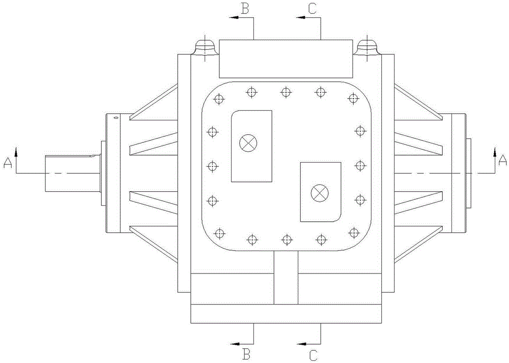
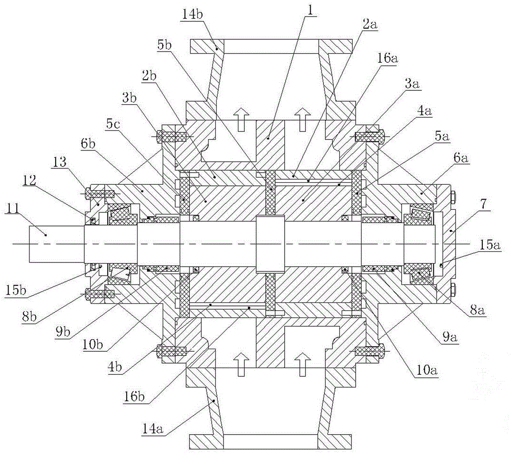
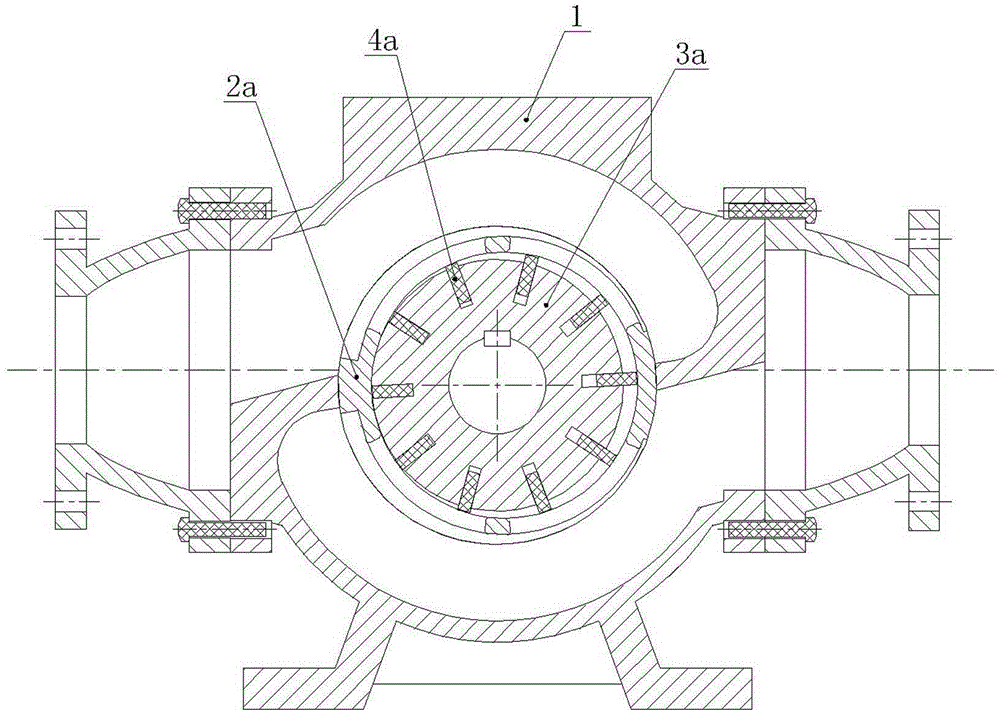
[0017] See attached figure 1 , attached figure 2 , a multi-stage high-flow sliding vane pump, including pump body (1), stator (2a / 2b), rotor (3a / 3b), sliding vane (4a / 4b), thrust plate (5a / 5b), Pump cover (6a / 6b), bearing rear gland (7), tapered roller bearing (8a / 8b), mechanical seal (9a / 9b), adjusting nut (10a / 10b), shaft (11), lip seal (12), bearing front gland (13), inlet and outlet reducing diameter (14a / 14b). The two stators (2a / 2b) with eccentric inner cavity are coaxial and 0 The phase difference is installed on the inner wall of the pump body (1), the two slotted rotors (3a / 3b) in the stator (2a / 2b) are coaxially installed on the shaft (11), and the thrust plate (5a / 5b) connects the two The rotors (3a / 3b) are separated, and the slides (4a / 4b) are slidably placed in the radial grooves of the rotors (3a / 3b), and the rotors (3a / 3b) pass through the ad...


PUM


Abstract

The invention discloses a multi-stage large-flow sliding vane pump. The multi-stage large-flow sliding vane pump is used for conveying various grease and chemical media. The multi-stage large-flow sliding vane pump mainly comprises a pump body, stators, rotors, sliding vanes, a shaft, pump covers, conical roller bearings and the like. The multi-stage large-flow sliding vane pump is characterized in that the two stators are coaxial and installed on the inner wall of the pump body with 1800 phase difference; the two rotors are installed on the shaft coaxially; double suction and double discharging are achieved, and the flow of the sliding vane pump is doubled; thrust plates, the stators, the rotors and the sliding vanes work in an cooperation mode to form two axially symmetrical sealed working cavities; two acting force in the opposite directions produced by the media conveyed by the sealed working cavities can be mutually offset, and medium pulsation is stable; the shaft is even in stress and does not bend, and the load of the conical roller bearings is reduced, so that the service life of the shaft and the conical roller bearings is prolonged; meanwhile, noise and vibration produced in the operation process of the pump are reduced. According to the multi-stage large-flow sliding vane pump, all the stators, the rotors, the sliding vanes and other core components are standard components, so that machining and maintenance are easy and the manufacturing cost is low.

Description

technical field [0001] The invention relates to a multi-stage large-flow sliding vane pump used for transporting various oils and chemical media. Background technique [0002] The sliding vane pump is a positive displacement pump with short self-priming time and high suction vacuum pressure that other pumps do not have. It is mainly used in all liquid loading and unloading conditions such as trains, liquid terminals, tankers, tank cars, and chemical tank dumping. Ordinary sliding vane pump mainly includes motor, coupling, and pump body assembly. The pump body assembly is mainly composed of pump cover, pump body, stator, rotor, sliding vane, shaft, bearing, bearing gland, etc. The flow rate of the vane pump is small; when the pump is driven by the motor, the rotating rotor will generate centrifugal force, which will cause the sliding vane to be thrown out of the rotor groove and slide along the inner surface of the stator. The thrust plate, stator, rotor, sliding vane Coope...

Claims


Application Information

Patent Timeline
Patent Type & Authority Applications(China)
IPC IPC(8): F04C2/344F04C15/06F04C11/00
CPCF04C2/3446F04C11/001F04C15/06
Inventor 王爱国
Owner BOTOU CITY GUANG TENG MACHINERY MFG
Why Eureka
Try Eureka