Valveless piezoelectric pump with separated driving structure and flow resistance structure and working method of valveless piezoelectric pump

A valveless piezoelectric pump and drive structure technology, which is applied to the components of pumping devices for elastic fluids, pumps with flexible working elements, pumps, etc. Problems such as poor fluidity and limited difference in flow resistance can achieve the effects of easy processing, strong reverse flow resistance and improved cooling performance.

Inactive Publication Date: 2021-08-10
NANTONG UNIVERSITY
View PDF4 Cites 0 Cited by
  • Summary
  • Abstract
  • Description
  • Claims
  • Application Information

AI Technical Summary

Problems solved by technology

[0003] Valveless piezoelectric pumps are generally divided into conical flow tube valveless piezoelectric pumps, Y-shaped flow tube valveless piezoelectric pumps, arc-shaped flow tube valveless piezoelectric pumps and asymmetric slope cavity bottom valveless piezoelectric pumps. , the valveless piezoelectric pump is basically a fluid drive device composed of an expansion flow tube, a compression flow tube and a piezoelectric vibrator. Poor flow resistance severely restricts the application of valveless piezoelectric pumps

Method used


Image

  • Valveless piezoelectric pump with separated driving structure and flow resistance structure and working method of valveless piezoelectric pump
  • Valveless piezoelectric pump with separated driving structure and flow resistance structure and working method of valveless piezoelectric pump
  • Valveless piezoelectric pump with separated driving structure and flow resistance structure and working method of valveless piezoelectric pump

Examples


Embodiment Construction

[0037] Specific embodiments of the present invention have been described above. It should be understood that the present invention is not limited to the specific embodiments described above, and those skilled in the art may make various changes or modifications within the scope of the claims, which do not affect the essence of the present invention.

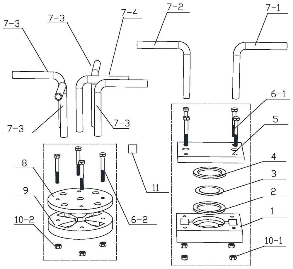
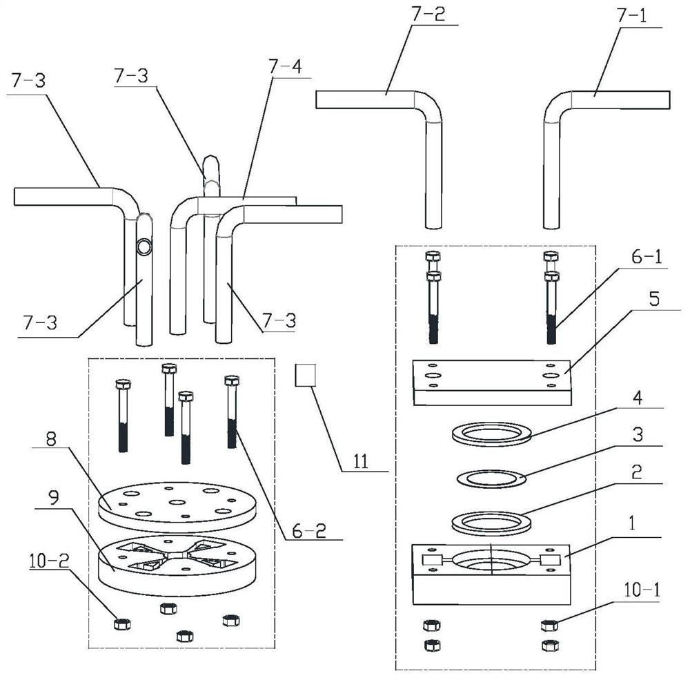
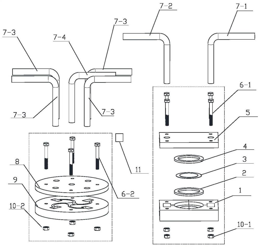
[0038] Such as Figure 1 to Figure 4 As shown, a valveless piezoelectric pump with separated drive and flow resistance structure, including drive structure, water inlet pipe I7-1, water outlet pipe I7-2, flow resistance structure, water inlet pipe II7-4 and multiple outlet pipes II7- 3;

[0039] The driving structure includes the pump base I1, the piezoelectric vibrator 3 and the pump cover I5, such as Figure 5 As shown, the middle of the pump base I1 is provided with a liquid chamber 1-5 and a pump chamber 1-4 from bottom to top, the piezoelectric vibrator 3 is placed in the pump chamber 1-4, and the piezoelectric vibrator 3 ...


PUM


Abstract

The invention discloses a valveless piezoelectric pump with separated driving structure and flow resistance structure and a working method of the valveless piezoelectric pump. The middle of a pump base I of the driving structure is provided with a liquid cavity and a pump cavity from bottom to top, a piezoelectric vibrator is placed in the pump cavity, buffer grooves I in the two ends of the pump base I are connected with the liquid cavity in the middle through direct current grooves, the lower end of a water inlet pipe I penetrates through a water inlet I of a pump cover I and is connected with a buffer tank I, and the lower end of a water outlet pipe I penetrates through a water outlet I of the pump cover I and is connected with the buffer tank I; and buffer grooves II at the two ends of a pump base II of the flow resistance structure are connected with a water storage area in the middle through flow pipes, the lower end of a water inlet pipe II penetrates through a water inlet II of a pump cover II to be connected with the water storage area, and the lower ends of a plurality of water outlet pipes II penetrate through a water outlet II of the pump cover II to be connected with the buffer grooves II. According to the pump, the water inlet pipes II and the water outlet pipes I are mutually connected to realize mutual connection of the flow resistance structure and the driving structure, and the plurality of flow pipes are arranged on the side of the flow resistance structure, so that the purposes of generating larger liquid one-way flow quantity and strong reverse flow stopping property in the same pressure difference are achieved.

Description

technical field [0001] The invention belongs to the technical field of fluid machinery, and more specifically relates to a valveless piezoelectric pump with separated driving and flow resistance structures and a working method thereof. Background technique [0002] The valveless piezoelectric pump is a product of multidisciplinary integration integrating fluid mechanics, material mechanics, vibration mechanics, electronics, mechanical design and theory. It has the advantages of simple structure, high pumping precision, no mechanical wear, strong anti-electromagnetic interference ability, etc., and has important application prospects in micro-electromechanical fields such as biomedicine, chip cooling, and fluid transportation. [0003] Valveless piezoelectric pumps are generally divided into conical flow tube valveless piezoelectric pumps, Y-shaped flow tube valveless piezoelectric pumps, arc-shaped flow tube valveless piezoelectric pumps and asymmetric slope cavity bottom va...

Claims


Application Information

Patent Timeline
Patent Type & Authority Applications(China)
IPC IPC(8): F04B43/04F04B53/16F04B53/00
CPCF04B43/046F04B43/023F04B43/0009F04B43/0027F04B53/16
Inventor 严秋锋
Owner NANTONG UNIVERSITY
Why Eureka
Try Eureka