Mobile vacuum boring and mud recovery method with the debris tank inclined & water storage below

a technology of mud recovery and vacuum boring, which is applied in the directions of transportation items, loading/unloading vehicles, and borehole/well accessories, etc., can solve the problems of consuming a lot of floor space, and achieve the effect of sufficient structural strength

Inactive Publication Date: 2006-02-16
BUCKNER LYNN ALLAN
View PDF17 Cites 43 Cited by
  • Summary
  • Abstract
  • Description
  • Claims
  • Application Information

AI Technical Summary

Benefits of technology

[0013] The above described objectives and others are met by a method comprising a device which will create a vacuum condition within a vacuum container and the vacuum container being mounted on a sufficient incline to allow debris to be empted out by gravity and to provide space beneath the debris tank to locate a water storage container and having a vacuum conduit to transport liquid and or solid particles into the vacuum container. A dispensing device may be added to dispense a liquid or a solid from the vacuum container without eliminating the vacuum environment within the vacuum container, and said vacuum container having the ability to fill, store and dispense its contents simultaneously. The vacuum container may further comprise a means to separate a liquid from solids. The vacuum conduit boom used to transport debris into the vacuum container may have the added feature of being an articulated powered vacuum conduit boom with sufficient structural strength to allow an operator to remotely move and control the location of the suction end of the vacuum conduit with one or more attachments adjacently attached to the suction end of said vacuum conduit and said attachments being chosen from an earth digging bucket, a telescoping vacuum conduit, sensor to locate buried utilities, monitors and controls to operate the attachments an their function, water spray nozzle, manhole cover remover, cutting tool, grinding tool, saw, blasting tool, surface cleaning tool, demolition tool, torque wrench, tractor to pull vacuum hose, jetter nozzle, or camera and power source to operate them.

Problems solved by technology

The vacuum tank, water tank, and other support equipment are each mounted separately on a trailer or truck bed, thus consuming a lot of floor space.

Method used


Image

  • Mobile vacuum boring and mud recovery method with the debris tank inclined & water storage below
  • Mobile vacuum boring and mud recovery method with the debris tank inclined & water storage below
  • Mobile vacuum boring and mud recovery method with the debris tank inclined & water storage below

Examples


first embodiment

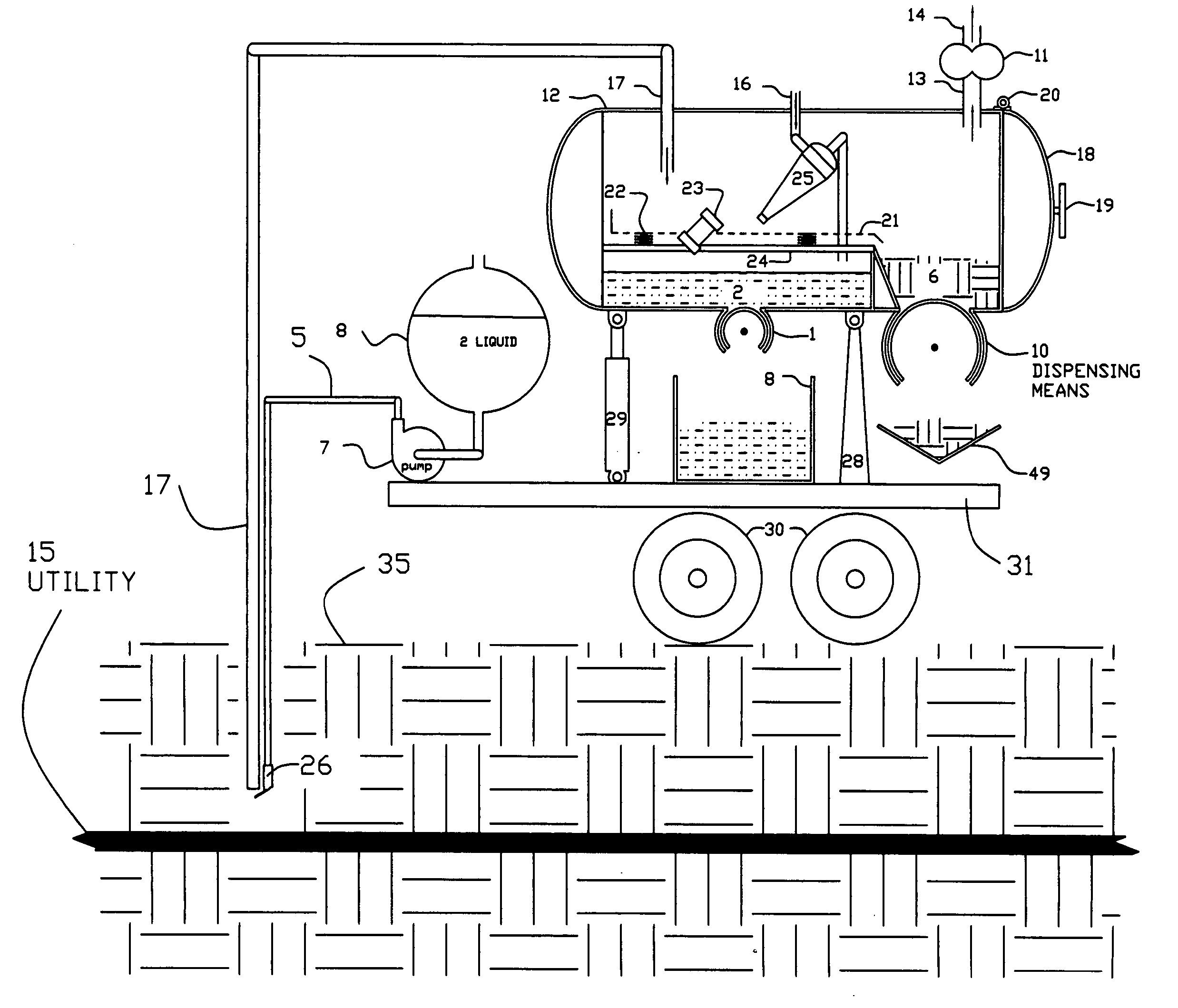
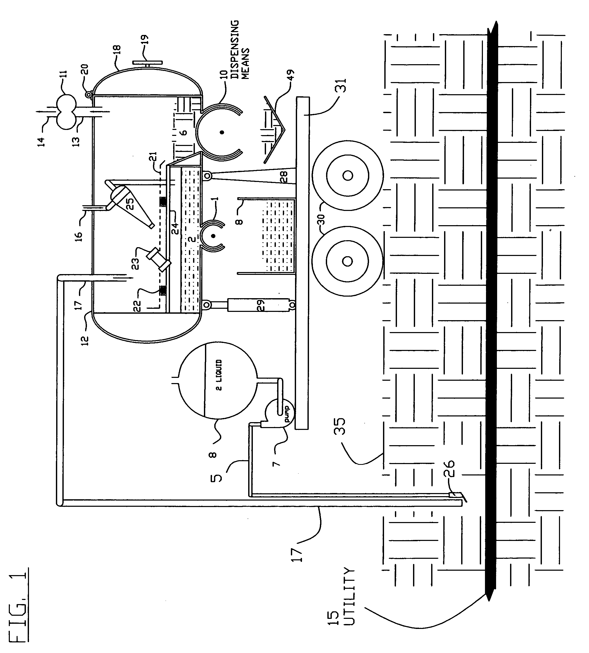
[0025]FIG. 1 shows the invention, being one example of various possible arrangements of apparatus within a vacuum container 12 for the purpose of accomplishing a method of separating solids 6 or liquids 2 by predetermined category and then dispensing said solids 6 or liquids 2 using a dispensing means 1 without eliminating the vacuum environment within the vacuum container 12. In FIG. 1, the apparatus of the present invention include a vacuum container 12, a vacuum producing means 11, a conduit 13 to allow air to move from vacuum container 12 to vacuum producing means 11, a second conduit 14 dispenses air from the vacuum producing means 11. Vacuum container 12 has an access door 18 having a hinge 20 and a latching means 19. Solids 6 or liquids 2 are vacuumed into vacuum container 12 by means of a vacuum conduit 17. In FIG. 1, the ground 35 is earthen dirt. Liquid 2, which has been stored in container 8, is pumped by pump 7 through pump discharge conduit 5 to a spray nozzle 26. The p...

second embodiment

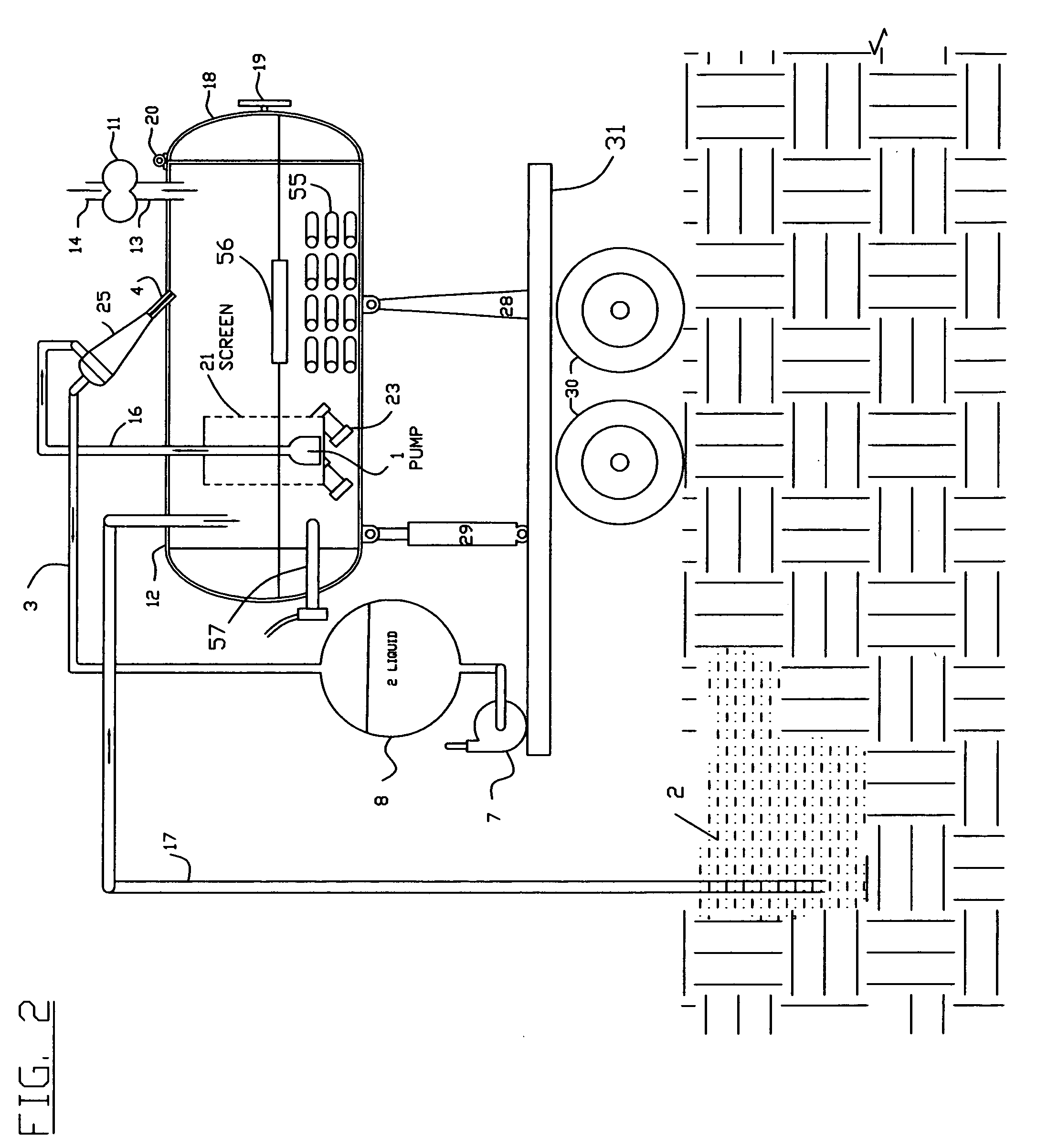
[0026] In the invention shown in FIGS. 2 and 3, the screen 21 is formed in the shape of a cylinder. The solids 6 and liquids 2 which are vacuumed through conduit 17, are deposited into vacuum container 12 around the vibrated screen well 21. The solids 6 which cannot pass through the screen well 21, remain in the vacuum container 12 to be dumped out through access door 18 when it is opened and cylinder 29 is extended. Liquid 2 passes through screen 21 thus dewatering the solids 6 which remain in vacuum container 12. Liquid 2, which passes through screen 21, is dispensed from vacuum container 12 by means of liquid dispenser 1, which in this example is a pump. The liquid 2 passes through conduit 16 and into hydrocyclone 25 where the solids 6 and liquid 2 separation is further refined. The solids 6 are discharged through solids discharge conduit 4 into vacuum container 12 and liquids are discharged through conduit 3 which discharges into a liquid 2 storage container 8 thus providing a m...

third embodiment

[0028] In the invention shown in FIG. 4, the solids 6 are passed through a solids grinder 27 in order to reduce the solids 6 size to a predetermined size before being dispensed by a solids dispenser 10 which in this example is a progressive cavity screw. The dispensed solids are collected in solids receiver container 9 to be hauled off. The liquid 2 is shown being dispensed by liquid dispenser means 1, which in this example is a diaphragm pump. The recycled liquid 2 is pumped through hose reel 37 by transfer pump 7 to a water jetter 39 spraying a water jet 40, thus cleaning drain pipe 38 with recycled water as it moves.

[0029] The recycled liquid 2 along with solids 6 washed from drain pipe 38 are vacuumed up by the vacuum conduit 17 which is shown as an articulated powered vacuum conduit boom 36. The articulated powered boom 36 also has means to place the jetter 39 into location down a manhole 59 and into a lateral drainage conduit 38 and dispense the jetter conduit 58. In this exam...


PUM


Abstract

A mobile vacuum boring and mud recovery method comprising a device which will create a vacuum condition within a vacuum container and the vacuum container is mounted on an incline to provide space beneath it to locate a water storage container, and having a vacuum conduit to transport a liquid and or solid particles into the vacuum container. The inclined vacuum tank facilitates gravitational assistance in both separation of liquids & solids as well as unloading debris. A dispensing device may be added to dispense a liquid or a solid from the vacuum container without eliminating the vacuum environment within the vacuum container, and said vacuum container having the ability to fill, store and dispense its contents simultaneously. The vacuum container may further comprises a means to separate a liquid from solids. The vacuum conduit articulated boom used to transport debris into the vacuum container may have the added feature or attachments chosen from an earth digging bucket, a telescoping vacuum conduit, sensor to locate buried utilities, monitors and controls to operate the attachments an their function, water spray nozzle, man hole cover remover cutting tool grinding tool, saw, blasting tool, surface cleaning tool, demolition tool, torque wrench, tractor to pull vacuum hose, jetter nozzle, or camera and power source to operate them. The above described vacuum system may be mounted on a variety of mobile platforms, chosen from but not limited to a trailer, truck, skid steer, fork lift, track hoe, railroad car, or zero turn radius vehicle which may have the added feature of being convertible between a powered vehicle & a trailer.

Description

[0001] This application claims the benefit of U.S. Non Provisional application Ser. No. 09 / 722,797 filed 27 Nov. 2000 and U.S. Non Provisional application Ser. No. 10 / 217,055 filed 12 Aug. 2002 to include it's 24 Sep. 2002 & 12 Mar. 2003 amendment and U.S. Provisional Application No. 60 / 363,058 filed on 11 Mar. 2002 and U.S. Provisional Application No. 60 / 384,719 filed on 3 Jun. 2002, which were parent cases of CIP Ser. No. 10 / 217,055BACKGROUND OF THE INVENTION [0002] 1. Field of the Invention [0003] The present invention relates to a vacuum boring and mud recovery method comprising a device which will create a vacuum condition within a vacuum container and the vacuum container is mounted on a sufficient incline to allow debris to be empted out by gravity and to provide space beneath the debris tank to locate a water storage container and having a vacuum conduit to transport a liquid and or solid particles into the vacuum container. A dispensing device may be added to dispense a liq...

Claims


Application Information

Patent Timeline
Patent Type & Authority Applications(United States)
IPC IPC(8): B60P1/00E21B21/06
CPCE02F3/8816E21B21/066E02F3/9268E02F3/9262Y10S37/905
Inventor BUCKNER, LYNN ALLAN
Owner BUCKNER LYNN ALLAN
Why Eureka
Try Eureka