A disc brake pump

A brake pump and disc brake technology, which is applied in the direction of brake actuators, gear transmission mechanisms, mechanical equipment, etc., can solve the problems of shortening the service life of the brake pump, achieve good brake response, accelerate recovery, and increase service life Effect

Active Publication Date: 2020-05-22
佛山飞羽动力科技有限公司
View PDF6 Cites 0 Cited by
  • Summary
  • Abstract
  • Description
  • Claims
  • Application Information

AI Technical Summary

Problems solved by technology

Moreover, the first sealing ring 102 on the brake piston 101 must seal the oil inlet hole 104 when performing braking, so that the first sealing ring 102 will be more worn, thereby shortening the service life of the brake pump

Method used


Image

  • A disc brake pump
  • A disc brake pump
  • A disc brake pump

Examples


Embodiment Construction

[0022] Specific embodiments of the present invention will be described in detail below in conjunction with the accompanying drawings. It should be understood that the specific embodiments described here are only used to illustrate and explain the present invention, and are not intended to limit the present invention.

[0023] Orientation words indicated by the terms "front", "rear", "upper", "lower", "left", "right", "top", "bottom", "inner", "outer", etc. in the description of the present invention All are based on the orientation or positional relationship shown in the drawings of the present invention, and are only for the convenience of describing the present invention and simplifying the description, therefore, they should not be construed as limiting the present invention.

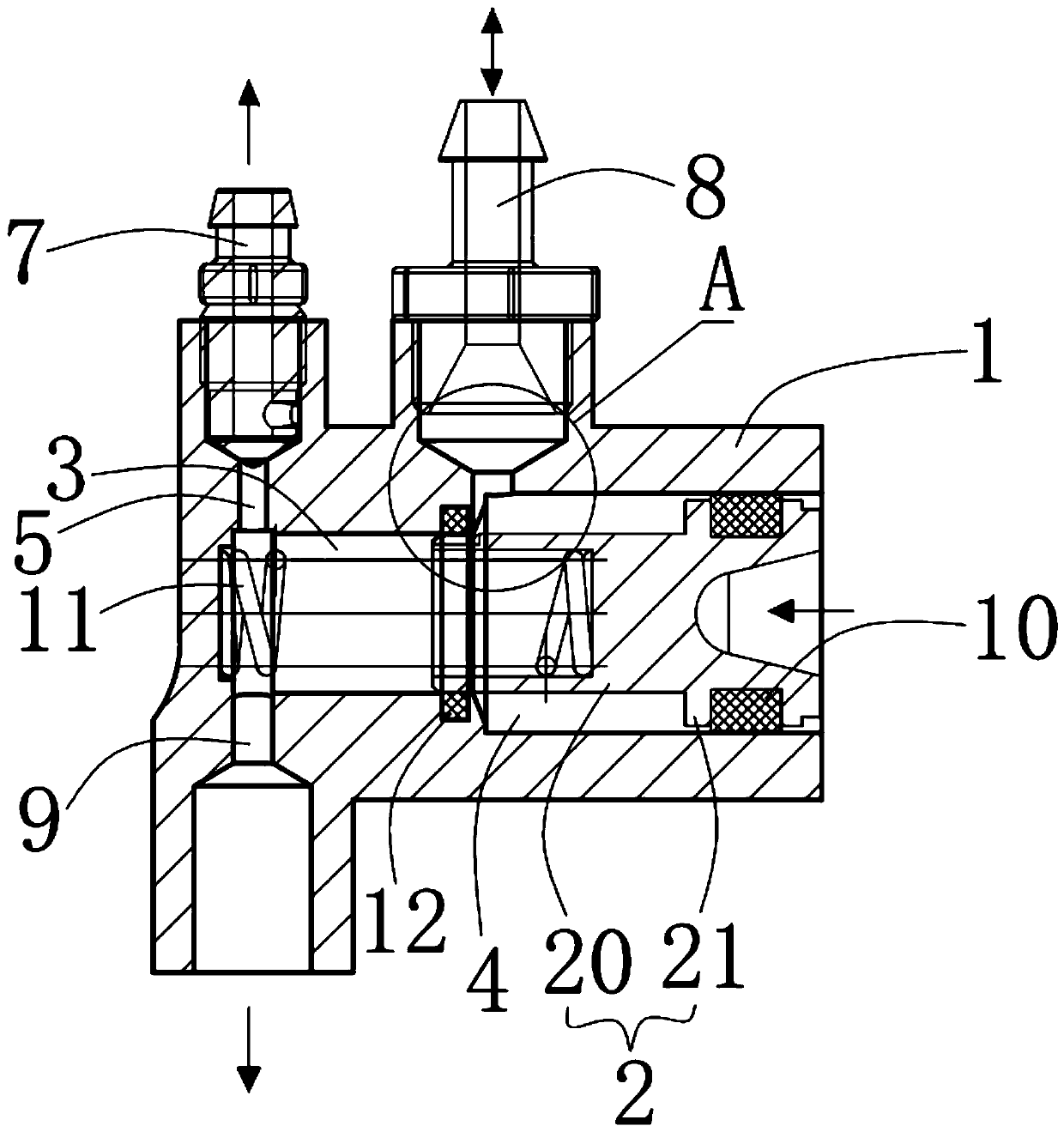
[0024] Such as Figure 2 to Figure 4 As shown, the disc brake pump of the present invention includes a pump body 1 and a piston 2 movably installed in the pump body 1 .

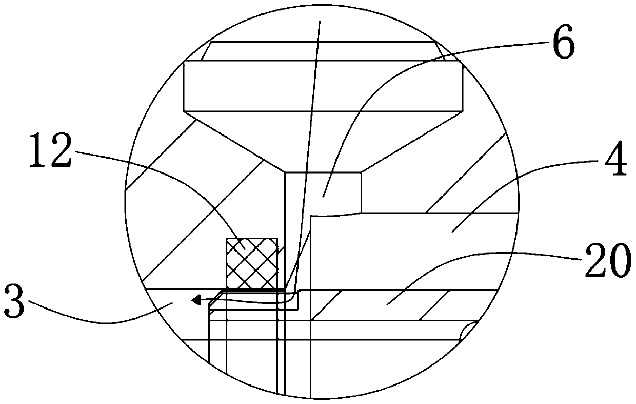
[0025] Such as Figure 4 ...


PUM


Abstract

The invention provides a disc brake pump comprising a pump body and a piston; and the pump body is provided with a first pressure cavity and a second pressure cavity, and the sectional area of the second pressure cavity is larger than the sectional area of the first pressure cavity. The upper end of the pump body is provided with an air outlet and an oil inlet, and the diameter of the oil inlet islarger than the diameter of the air outlet; and the lower end of the pump body is provided with an oil outlet, and the oil outlet and the air outlet are located on the same perpendicular line. The piston comprises a piston rod and a stopper plug which are formed integrally; the stopper plug is provided with a first sealing ring in a sleeved manner, and the first sealing ring is used for sealing aclearance between the stopper plug and the second pressure cavity; the end, far away from the stopper plug, of the piston rod is concavely provided with a groove; and the inner wall of the first pressure cavity is provided with a second sealing cavity which is close to the second pressure cavity. The disc brake pump has the advantages of quick rising of braking fluid, consistent braking responseand long service life.

Description

technical field [0001] The invention relates to the technical field of motor vehicle equipment components, in particular to a disc brake pump. Background technique [0002] Such as figure 1 As shown, the existing brake pump includes a pump body 100 and a brake piston 101 located in the pump body 100. Since the free stroke of the brake pump 100 is too large, the braking response is not consistent. The first sealing ring 102 and the second sealing ring 103 are arranged on it, and the structure is relatively complicated. [0003] In addition, the upper end of the pump body 100 defines an oil inlet hole 104 for the brake fluid to flow in. Since the oil inlet hole 104 is small, the brake fluid rises slowly. Therefore, it is necessary to open a compensation hole 105 on the pump body 100 to balance the pressure of the pressure chamber in the brake piston 101 . Moreover, the first sealing ring 102 on the brake piston 101 must seal the oil inlet hole 104 during braking, so that th...

Claims


Application Information

Patent Timeline
Patent Type & Authority Patents(China)
IPC IPC(8): F16D65/14F16D121/04F16D125/02F16D125/06F16D125/08
CPCF16D65/14F16D2121/04F16D2125/023F16D2125/06F16D2125/08
Inventor 吴尤利
Owner 佛山飞羽动力科技有限公司
Why Eureka
Try Eureka