
Self-locking electronic mechanical braking device

An electro-mechanical brake and self-locking technology, which is applied in the direction of mechanical equipment, brake types, brake actuators, etc., can solve the unfavorable high integration requirements of the emerging automobile industry, and it is difficult to meet the requirements of automobile parking brakes, Insufficient structural optimization and other problems, to achieve good braking response, good braking stability, and convenient layout

Pending Publication Date: 2017-10-24
JILIN UNIV
View PDF15 Cites 21 Cited by
  • Summary
  • Abstract
  • Description
  • Claims
  • Application Information

AI Technical Summary

Problems solved by technology

[0005] Due to the large number of components of the existing electromechanical braking device, the structural optimization is not reasonable enough, resulting in a large volume and low integration of the electromechanical braking device, which is not conducive to the high integration of the emerging automobile industry. Requirements; In addition, the current electromechanical brake devices lack independent self-locking mechanisms, and it is difficult to meet the braking requirements when the car is parked.

Method used


Image

  • Self-locking electronic mechanical braking device
  • Self-locking electronic mechanical braking device
  • Self-locking electronic mechanical braking device

Examples


specific Embodiment approach

[0036] In order to further clearly illustrate the technical solution of the present invention, in conjunction with the accompanying drawings, the specific implementation of the present invention is as follows:

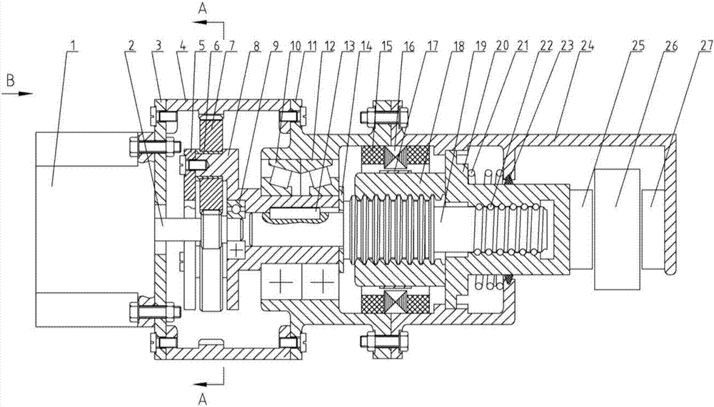
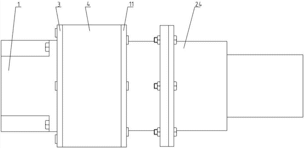
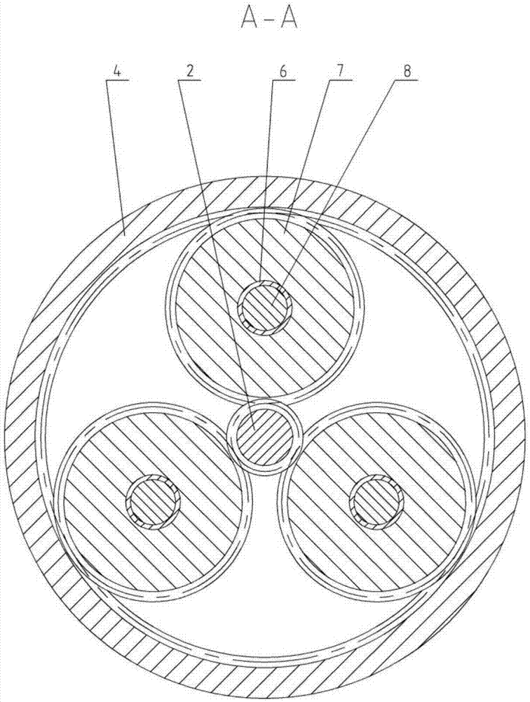
[0037] Such as figure 1 As shown, the present invention provides a self-locking electromechanical braking device, which mainly consists of a first motor 1, a motor output shaft 2, a case cover 3, a front case body 4, a cover plate 5, a bearing bush 6, a planetary gear 7, Planet carrier 8, deep groove ball bearing 9, first tapered roller bearing 10, intermediate case 11, second tapered roller bearing 12, flat key 13, bushing 14, stator core 15, stator winding 16, rotor magnet Yoke 17, second motor rotor 18, screw shaft 19, ball screw nut 20, spring 21, ball screw ball 22, sealing ring 23, rear box 24, first friction plate 25, brake disc 26 And the second friction plate 27 is formed.

[0038] The first motor 1 is a DC brushless motor, such as Figure 4 As shown, the r...


PUM


Abstract

The invention provides a self-locking electronic mechanical braking device. The braking device consists of a box, a first motor, a planet gear transmission mechanism, a lead screw shaft, a second motor, a ball screw pair nut, a spring, friction plates and a brake disc; the first motor is mounted on the box; a sun gear of the planet gear transmission mechanism is arranged on a motor output shaft; a gear ring is fixed in the box; a planet carrier is coaxially connected with the lead screw shaft; the muddle part of the lead screw shaft and a second motor rotor are mounted to form a slide lead screw pair; a second motor stator is fixedly mounted on the inner side of the box; the other end of the lead screw shaft and the ball screw pair nut are mounted to form a ball screw pair; the ball screw pair nut penetrates through the box; the spring is mounted between the ball screw pair nut and the box; two friction plates are respectively mounted on separation plates on the outer sides of the ball screw pair nut and the box; and the brake disc is mounted between the two friction plates. The braking device can effectively save the volume in overall vehicle arrangement, and can stably realize self-locking function.

Description

technical field [0001] The invention belongs to the technical field of automobile brake systems. More specifically, the present invention relates to a self-locking electromechanical braking device. Background technique [0002] Traditional automobile brake systems usually use hydraulic brake devices, which have the disadvantage of requiring a certain number of pipelines and valve components, making the whole device complex in structure and heavy in mass. Due to the long pipeline of the hydraulic brake device, the brake pressure is generated slowly, and it is easy to cause brake lag, which makes the time to eliminate the brake gap longer, resulting in reduced safety; if you want to obtain a faster brake response, hydraulic pressure Braking device just must adopt high-performance hydraulic valve element, promptly increased the cost of braking system itself. [0003] With the overall high-speed development of the current automobile industry, people have put forward higher req...

Claims


Application Information

Patent Timeline
Patent Type & Authority Applications(China)
IPC IPC(8): F16D55/224F16D65/14F16D121/14F16D121/24F16D123/00F16D125/40F16D125/50
CPCF16D55/224F16D65/14F16D2121/14F16D2121/24F16D2123/00F16D2125/50F16D2125/40
Inventor 李静刘鹏丁万兴
Owner JILIN UNIV
Learn More