View angle switchable liquid crystal display device and view angle switching method thereof

A liquid crystal display device and viewing angle technology, which is applied in static indicators, instruments, nonlinear optics, etc., can solve the problems of increased thickness and cost of liquid crystal displays, complicated manufacturing process, and does not conform to the development trend of thin and light liquid crystal displays, etc. The effect of operational flexibility and convenience

Active Publication Date: 2016-03-23
KUSN INFOVISION OPTOELECTRONICS
View PDF6 Cites 51 Cited by
  • Summary
  • Abstract
  • Description
  • Claims
  • Application Information

AI Technical Summary

Problems solved by technology

[0005] However, the disadvantage of the above-mentioned first method is that this method requires an additional louver shielding film, which needs to be carried by the user, which causes great inconvenience to the user, and can only realize narrow viewing angle display after the anti-peeping film is pasted. mode; the defect of the above-mentioned second method is that this kind of dual-light source backlight system will cause the thickness and cost of the liquid crystal display to increase, which is not in line with the development trend of thinning and thinning of the liquid crystal display; the defect of the above-mentioned third method is that the liquid crystal display device needs to There are two kinds of electrodes, the wide viewing angle display driving electrode and the viewing angle control electrode, which reduce the aperture ratio of the liquid crystal display device, resulting in a decrease in the brightness of the panel of the liquid crystal display device and making the manufacturing process more complicated.

Method used


Image

  • View angle switchable liquid crystal display device and view angle switching method thereof
  • View angle switchable liquid crystal display device and view angle switching method thereof
  • View angle switchable liquid crystal display device and view angle switching method thereof

Examples


Embodiment Construction

[0030] In order to further illustrate the technical means and effects adopted by the present invention to achieve the predetermined purpose of the invention, the specific embodiments, structures, features and effects of the present invention are described in detail below in conjunction with the accompanying drawings and examples.

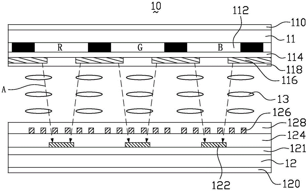
[0031] Please refer to figure 1 The liquid crystal display device 10 provided in this embodiment includes a first substrate 11 , a second substrate 12 disposed opposite to the first substrate 11 , and a liquid crystal layer 13 located between the first substrate 11 and the second substrate 12 . The liquid crystal display device 10 is suitable for liquid crystal display devices such as In-Plane Switching (IPS) and Fringe Field Switching (FFS) in which liquid crystal molecules rotate in a plane parallel to the substrate when an electric field for display is applied. . In this embodiment, the liquid crystal display device 10 is described by taking a f...


PUM


Abstract

The invention discloses a view angle switchable liquid crystal display device and a view angle switching method thereof. The view angle switchable liquid crystal display device comprises a first substrate, a second substrate and a liquid crystal layer located between the first substrate and the second substrate, wherein multiple sub-pixel areas are limited on the second substrate, first electrodes are arranged on the surface, facing the liquid crystal layer, of the first substrate, second electrodes and third electrodes are arranged on the surface, facing the liquid crystal layer, of the second substrate, each first electrode comprises a first common connecting wire and a plurality of first electrode strips formed through extending of the first common connecting wire, each second electrode is a common electrode and comprises a second common connecting wire and a plurality of second electrode strips formed through extending of the second common connecting wire, the first electrode strips and the second electrode strips are arranged in a staggered manner, each second electrode strip is arranged in the middle of each sub-pixel area, the first electrode strips are arranged on two sides of each second electrode strip, the first electrode strips and the second electrode strips are not overlapped, each third electrode is a pixel electrode and is arranged in each sub-pixel area, and liquid crystal molecules in the liquid crystal layer are negative liquid crystal molecules.

Description

technical field [0001] The present invention relates to the technical field of liquid crystal display, and in particular, to a liquid crystal display device with a switchable viewing angle and a viewing angle switching method thereof. Background technique [0002] Liquid crystal display (LCD) has the advantages of good picture quality, small size, light weight, low driving voltage, low power consumption, no radiation and relatively low manufacturing cost, and is dominant in the field of flat panel display. [0003] Now liquid crystal display devices are gradually developing towards a wide viewing angle direction. For example, a liquid crystal display device using in-plane switching mode (IPS) or fringe field switching mode (FFS) can achieve a wider viewing angle. The wide viewing angle design allows users to see a complete and undistorted picture from all directions. However, in today's society, people pay more and more attention to protecting their privacy, and there are m...

Claims


Application Information

Patent Timeline
Patent Type & Authority Applications(China)
IPC IPC(8): G02F1/1343G02F1/1345G02F1/133
CPCG02F1/13306G02F1/134309G02F1/134363G02F1/13452G02F1/134372G02F1/1323G02F1/134381
Inventor 姜丽梅江雪梅吴婷婷刘瑞
Owner KUSN INFOVISION OPTOELECTRONICS
Why Eureka
Try Eureka