
Voltage boost control method of switching power supply

A switching power supply, boost control technology, applied in the direction of collectors, electric vehicles, electrical components, etc., can solve the problem of uncontrollable output of boost power supply, achieve controllable output voltage range, reduce ripple, boost range can be controlled. control effect

Inactive Publication Date: 2016-03-23
苏州扬佛自动化设备有限公司
View PDF6 Cites 0 Cited by
  • Summary
  • Abstract
  • Description
  • Claims
  • Application Information

AI Technical Summary

Problems solved by technology

[0006] The technical problem to be solved by the present invention is to provide a boost control method of switching power supply, which solves the problem of uncontrollable output of boost power supply in the prior art

Method used


Image

  • Voltage boost control method of switching power supply

Examples


Embodiment Construction

[0018] The structure and working process of the present invention will be further described below.

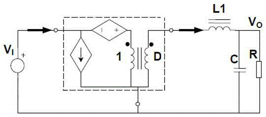
[0019] like figure 1 As shown, a step-up control method for a switching power supply, the switching power supply includes an AC filter module, a rectifier module, a DC / DC module, a control module, an output filter and voltage regulator module, an output detection circuit, and a relay, and the AC filter module It is used to filter the mains power, the rectifier module is used to convert AC power to DC power, the DC / DC module is used to convert DC power to voltage, the control module is used to control the charging current and voltage, and the output filter voltage stabilization module is used for The output voltage is filtered and stabilized, the output detection circuit is used to detect the output current, the relay is used to control the on and off of the input terminal AC, and a coupling inductor is also included, and the coupling inductor is set between the DC / DC module and...


PUM


Abstract

The invention discloses a voltage boost control method of a switching power supply. The switching power supply comprises an AC filtering module, a rectification module, a DC / DC module, a control module, an output filtering voltage stabilizing module, an output detection circuit and a relay and also comprises a coupling inductor. The coupling inductor is arranged between the DC / DC module and the output filtering voltage stabilizing module. The coupling inductor comprises a first winding and a second winding. The first winding and the second winding are variable resistors. The range of the turn ratio of the first winding to the second winding is controlled to be 1-3. The adjustable voltage boost range can be realized by controlling the turn ratio of the two windings so that the voltage boost range of the switching power supply is enabled to be controllable, and degree of intellectualization is enhanced.

Description

technical field [0001] The invention belongs to the application field of power supply circuits, and in particular relates to a boost control method of a switching power supply. Background technique [0002] Charging power supply chargingsupply rectification device for battery charging. In the early stage, AC motor-DC generator set (also known as rotary unit) was used as the charging power source. After the 1960s, it was replaced by a charging power source composed of power electronic devices. The charging power supply often adopts a single-phase (or three-phase) semi-controlled rectifier circuit (composed of a mixture of thyristors and diodes, and the load voltage cannot be reversed) or an uncontrolled rectifier circuit (composed of rectifier diodes without control kinetic energy) plus an AC voltage regulator In the rectifier circuit, in the DC circuit, a smoothing reactor is required to suppress the DC current pulsation and prevent the current from being interrupted. [0...

Claims


Application Information

Patent Timeline
Patent Type & Authority Applications(China)
IPC IPC(8): H02J7/04H02M3/04
CPCH02J7/022H02J7/027H02J7/04H02M3/04
Inventor 孙向琳刘厚成
Owner 苏州扬佛自动化设备有限公司
Learn More