
Vehicle control device

A technology for vehicle control devices and service brakes, which is applied to control devices, off-road vehicles, vehicle components, etc., and can solve problems such as large shaking, inability to drive, and vehicle rushing out

Active Publication Date: 2016-03-23
ADVICS CO LTD
View PDF9 Cites 3 Cited by
  • Summary
  • Abstract
  • Description
  • Claims
  • Application Information

AI Technical Summary

Problems solved by technology

[0004] However, even if the idling suppression control is performed by reducing the allowable slippage, if the accelerator pedal is not depressed in order to overcome road surface resistance such as a slope of the road surface and a step difference, it will not be possible to drive smoothly off-road or on a slope.
That is, on off-road and steeply inclined slopes such as gravel roads, since the running state of the vehicle changes moment by moment, and the vehicle body shakes greatly as the vehicle travels, the driver responds accordingly to the changing running state. Proper acceleration and braking operations are difficult
Therefore, in the control such as the device described in Patent Document 1, which reflects the acceleration and braking operations as they are in the driving force and braking force, and suppresses the acceleration after the start of slipping, it is impossible to run smoothly on off-road or on slopes.
In particular, there are cases where the driver's intention and the acceleration and deceleration of the vehicle deviate, such as when the vehicle rushes out after overcoming an obstacle, or when the vehicle accelerates on a steep downhill slope.

Method used

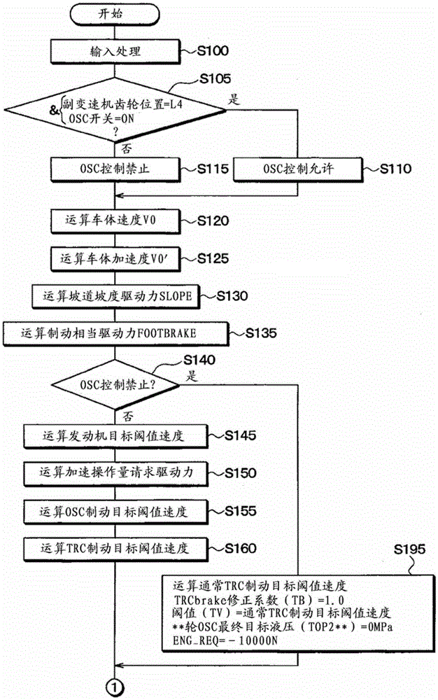
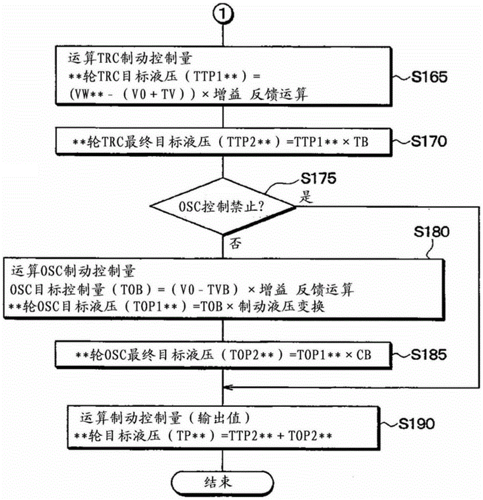

Image

  • Vehicle control device
  • Vehicle control device
  • Vehicle control device

Examples


no. 1 approach

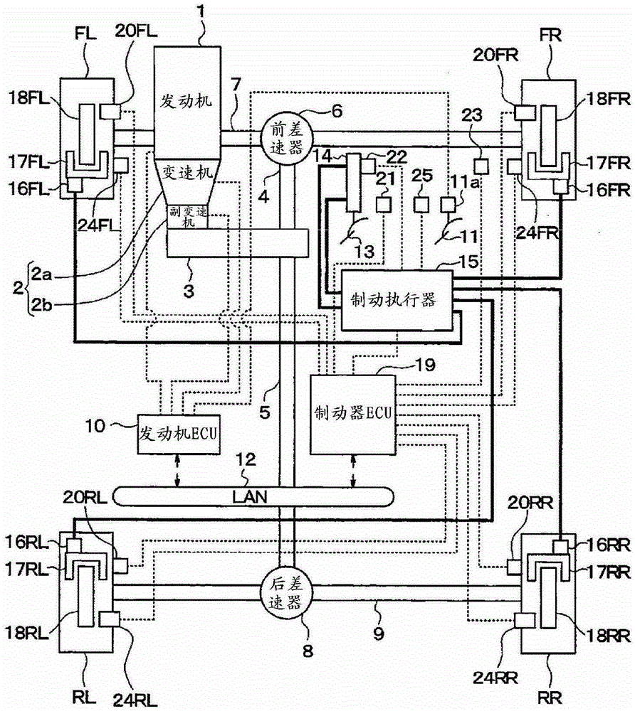
[0034] figure 1 It is a diagram showing a system configuration of a braking and driving system of a vehicle to which the vehicle control device according to the first embodiment of the present invention is applied. Here, a vehicle posture control device according to an embodiment of the present invention is applied to a four-wheel drive vehicle in which the front wheels are driven as the main base in a driving system in which the front wheels are used as main driving wheels and the front wheels are used as driven wheels. However, it can also be applied to a four-wheel drive vehicle based on a rear-wheel drive base in which the rear wheel side is used as the main drive wheel and the front wheel side is used as the driven wheel.

[0035] Such as figure 1 As shown, the drive system of a 4-wheel drive vehicle has an engine 1, a transmission 2, a driving force distribution control actuator 3, a front drive shaft 4, a rear drive shaft 5, a front differential 6, a front drive shaft ...


PUM


Abstract

To enable control of the speed of a vehicle according to the intentions of a driver by means of a simpler operation. In the present invention, when a vehicle body speed (V0) rapidly decreases and becomes lower than a brake target threshold speed (TVB), the brake target threshold speed (TVB) is decreased in conformity with the vehicle body speed (V0). The present invention can thereby prevent the increase of the vehicle body speed (V0) toward the brake target threshold speed (TVB) such that a vehicle accelerates regardless of a brake being in operation because the brake target threshold speed (TVB) is set at a higher value than the vehicle body speed (V0). Accordingly, the present invention causes the vehicle body speed (V0) to decelerate by means of a simpler operation while being able to prevent the vehicle from accelerating against the intentions of a driver and being able to control the speed of the vehicle according to the intentions of the driver.

Description

technical field [0001] The present invention relates to a vehicle control device capable of smoothly running a vehicle, and is suitable for running on a road surface that may hinder the running of the vehicle, such as off-road and slopes. Background technique [0002] Conventionally, in Patent Document 1, it is disclosed that for the purpose of improving the passability in off-road, when the gear of the auxiliary transmission equipped on the four-wheel drive vehicle is a low-speed gear, the allowable slippage of the driving wheel is reduced. Vehicle traction control device. In this device, slippage suppression control is performed by reducing the allowable slippage of the drive wheels, so that traction force control that emphasizes trafficability according to the driver's intention can be performed. [0003] Patent Document 1: Japanese Patent Laid-Open No. 2000-344083 [0004] However, even if the idling suppression control is performed by reducing the allowable slip, if t...

Claims


Application Information

Patent Timeline
Patent Type & Authority Applications(China)
IPC IPC(8): B60T7/12B60W10/04B60W10/06B60W10/18B60W10/188B60W30/188
CPCB60T7/12B60W10/06B60W30/188B60W10/184B60W30/18063B60W30/18172B60W30/182B60W2300/185B60W2540/10B60W2540/106B60W2710/18B60W2720/10B60W2540/215B60W2552/15B60T8/3205B60W10/04B60W10/18B60W10/188B60T8/175
Inventor 石田康人
Owner ADVICS CO LTD
Learn More