Rotor nozzle for a high-pressure cleaning apparatus

a technology of cleaning apparatus and nozzle body, which is applied in the direction of cleaning process and apparatus, cleaning using liquids, chemistry apparatus and processes, etc., can solve the problems of affecting the rotational speed of the nozzle body in its rotational movement about the longitudinal axis of the housing, and affecting the cleaning effect of the liquid jet. , to achieve the effect of cost-effective production and convenient housing shaping

Inactive Publication Date: 2017-12-21
ALFRED KARCHER GMBH & CO KG
View PDF5 Cites 0 Cited by
  • Summary
  • Abstract
  • Description
  • Claims
  • Application Information

AI Technical Summary

Benefits of technology

[0009]In the rotor nozzle according to the invention, a guiding surface is arranged upstream of each baffle surface, which guiding surface is continuously adjoined by the respective baffle surface in the flow direction of the liquid. The guiding surfaces are aligned obliquely to a radial plane with respect to the longitudinal axis of the housing. The oblique alignment of the guiding surfaces has the consequence that revolving liquid is supplied along the guiding surfaces to the baffle surfaces, which oppose the revolving movement of the liquid. A significant deceleration of the liquid flow can thereby be achieved and this, in turn, has the consequence that the rotational speed that the nozzle body has in its rotational movement about the housing longitudinal axis can be limited effectively.
[0032]The following description of two advantageous embodiments of the invention serves the more detailed explanation in connection with the drawing. Shown are:

Problems solved by technology

A significant deceleration of the liquid flow can thereby be achieved and this, in turn, has the consequence that the rotational speed that the nozzle body has in its rotational movement about the housing longitudinal axis can be limited effectively.
In the region between the at least one inlet of the housing and the support surface, no flow resistance elements are arranged, which could impair the movement of the liquid.
This results in an additional fanning out of the liquid jet, which fanning out impairs the cleaning effect of the liquid jet.

Method used


Image

  • Rotor nozzle for a high-pressure cleaning apparatus
  • Rotor nozzle for a high-pressure cleaning apparatus
  • Rotor nozzle for a high-pressure cleaning apparatus

Examples


Embodiment Construction

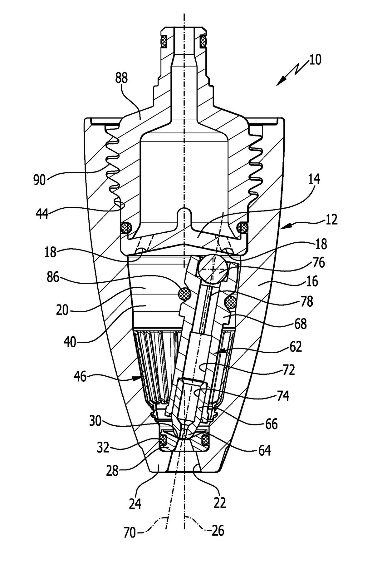
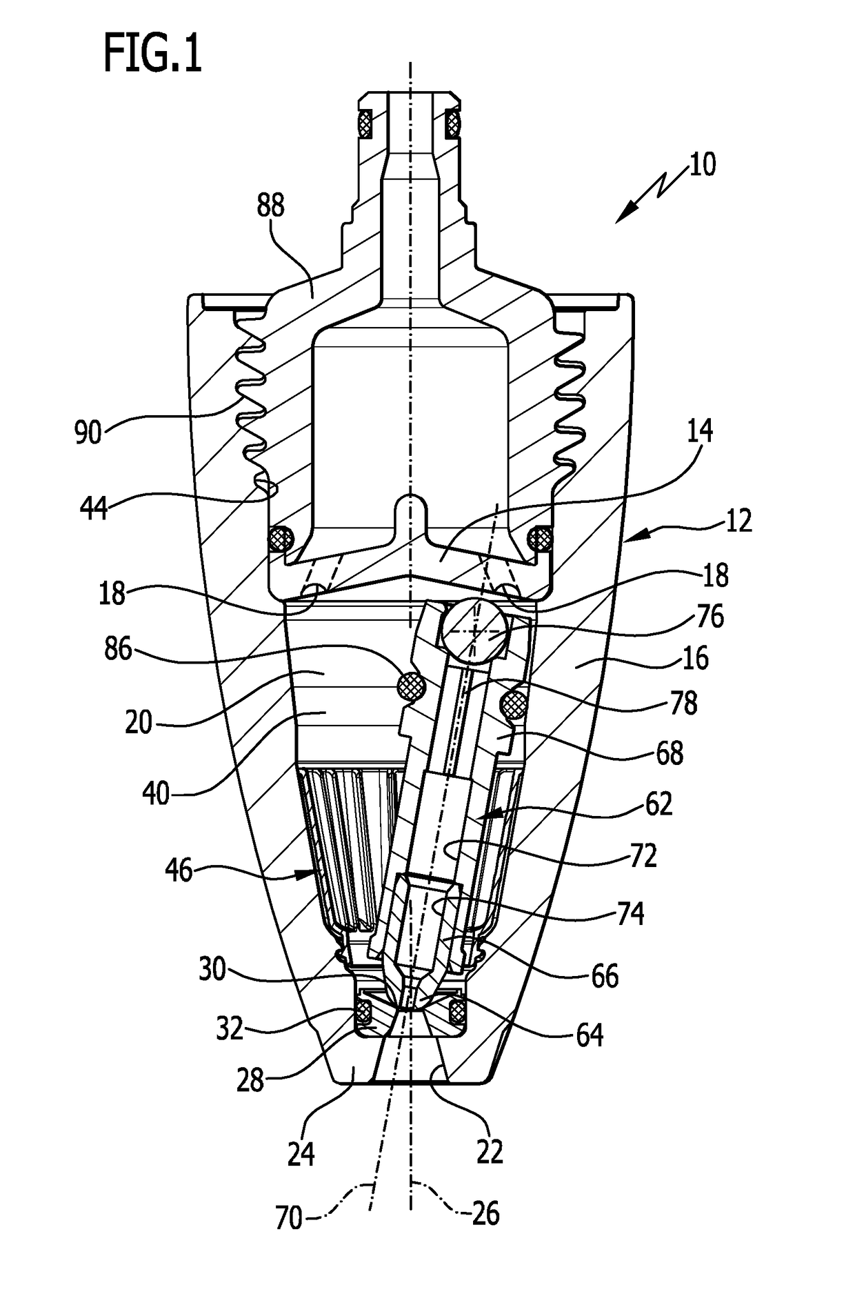
[0039]FIGS. 1 to 4 schematically show a first advantageous embodiment of a rotor nozzle according to the invention, which rotor nozzle is overall denoted by the reference symbol 10. The rotor nozzle 10 has a housing 12 with a housing bottom 14 and a housing lid 16. The housing bottom 14 is designed to be disk-shaped and has several tangential inlets 18, which open into an internal space 20 of the housing 12. The internal space 20 is surrounded by the housing lid 16 and tapers starting from the tangential inlets 18 toward an outlet 22, which is arranged on an end wall 24 of the housing lid 16.

[0040]Via the tangential inlets 18, pressurized liquid can be supplied to the internal space 20, which liquid rotates about a housing longitudinal axis 26 in the internal space 20 and can exit the housing 12 via the outlet 22.

[0041]Directly upstream of the outlet 22, a bearing in the form of a bearing ring 28 is arranged in the internal space 20, which bearing ring forms a pan-shaped recess 30. ...


PUM


Abstract

A rotor nozzle for a high-pressure cleaning apparatus is provided, with a housing having an inlet opening tangentially into the housing and an outlet arranged on an end wall and on which is arranged a pan-shaped, centrally broken recess. A nozzle body arranged in the housing, having a through channel, and supported with a spherical end in the pan-shaped recess has a longitudinal axis tilted toward the longitudinal axis of the housing. The nozzle body is brought into a revolving movement by liquid flowing through the housing and supported on a support surface, of which flow resistance elements, each having one baffle surface, are arranged downstream of on the wall of the housing. A guiding surface is arranged upstream of each baffle surface and is continuously adjoined by the baffle surface, wherein the guiding surface is aligned obliquely to a radial plane of the housing.

Description

CROSS-REFERENCE TO RELATED APPLICATIONS[0001]This application is a continuation of international application number PCT / EP2015 / 054310 filed on Mar. 2, 2015, which is incorporated herein by reference in its entirety and for all purposes.BACKGROUND OF THE INVENTION[0002]The invention relates to a rotor nozzle for a high-pressure cleaning apparatus with a housing having at least one inlet opening tangentially into the housing and an outlet which is arranged on an end wall of the housing and on which is arranged a bearing with a pan-shaped, centrally broken recess, and with a nozzle body which is arranged in the housing, has a through channel, and is supported with a spherical end in the pan-shaped recess, the longitudinal axis of which nozzle body is tilted toward the longitudinal axis of the housing and which nozzle body is brought into a revolving movement by the liquid flowing through the housing, in which revolving movement the longitudinal axis of the nozzle body revolves on a con...

Claims


Application Information

Patent Timeline
Patent Type & Authority Applications(United States)
IPC IPC(8): B05B3/04B05B1/02
CPCB05B1/02B05B3/0463B08B3/026B05B3/0418
Inventor DIRNBERGER, SVENSCHWARZ, BJOERNWERNER, STEFANWESCH, JOHANN GEORG
Owner ALFRED KARCHER GMBH & CO KG
Why Eureka
Try Eureka