Method for operating a brake system, and brake system

a technology of brake system and brake system, which is applied in the direction of braking system, control system, etc., can solve the problems of affecting the operation of the brake system, the braking force may increase very rapidly, and the subsurface may become markedly too large, so as to achieve control quickly and high dynamic performance

Active Publication Date: 2021-09-09
ROBERT BOSCH GMBH
View PDF2 Cites 0 Cited by
  • Summary
  • Abstract
  • Description
  • Claims
  • Application Information

AI Technical Summary

Benefits of technology

[0016]A setpoint value of the brake pressure may be controlled individually per wheel brake cylinder by using the precontrol value and a wheel speed of the wheel braked by the wheel brake cylinder. A wheel speed may be detected directly on the wheel. The wheel speeds of different wheels may differ. The wheel speed may be detected with a high dynamic performance. In contrast to the slip, which can only be estimated indirectly, the wheel speed may be measured directly. By using the derivative of the wheel speed it is possible to achieve control quickly. If the wheel speed falls too rapidly, the wheel will soon experience excessive slip.
[0017]The setpoint value may be set during initial brake application time in accordance with the precontrol value. Following the expiration of the initial brake application time, the setpoint value may be controlled using the precontrol value and the derivative of the wheel speed. At the beginning of the initial brake application process, a highly dynamic transient effect occurs due to properties of the suspension and of the tires, which is detected via the wheel speed. In order to suppress this for the control process, the wheel speed may be ignored until a predetermined initial brake application time. Following the initial brake application time, the control process may be started by using the wheel speed.

Problems solved by technology

When braking sharply, that is, when the brake pedal is depressed very quickly for example, the braking force increases very rapidly and may become markedly too high for the respective subsurface.
The slip may then become very great and the wheel may lock.
During this time, the vehicle is not decelerated optimally.
If the wheel speed falls too rapidly, the wheel will soon experience excessive slip.

Method used


Image

  • Method for operating a brake system, and brake system
  • Method for operating a brake system, and brake system
  • Method for operating a brake system, and brake system

Examples


Embodiment Construction

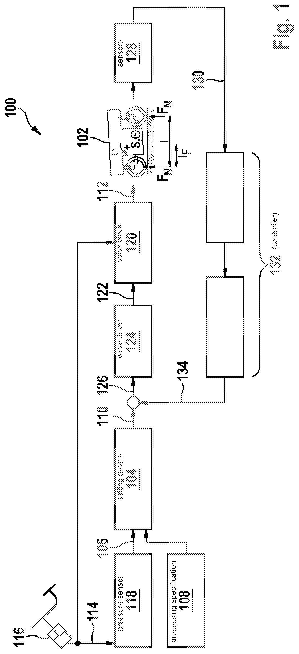
[0030]FIG. 1 shows a block diagram of a brake system 100 of a vehicle 102 according to one exemplary embodiment. Brake system 100 is designed to carry out a method according to the approach presented here. For this purpose, brake system 100 has a setting device 104, in which a precontrol value 110 is set for a brake pressure 112 of brake system 100 by using an admission pressure value 106 and a processing specification 108. Admission pressure value 106 represents an admission pressure 114 in brake system 100, while processing specification 108 represents a braking dynamics of vehicle 102.

[0031]Admission pressure value 106 is detected by a pressure sensor 118 situated between a master brake cylinder 116 of vehicle 102 and brake system 100 and is provided as an electrical signal or data word for device 104.

[0032]Using the precontrol value 110, brake pressure 112 is set in a valve block 120 of brake system 100. For this purpose, valve block 120 is hydraulically connected to master bra...


PUM


Abstract

A method for operating a brake system of a vehicle. A precontrol value for a brake pressure of the brake system is set by using an admission pressure value representing a admission pressure in the brake system and a processing specification representing a braking dynamics of the vehicle.

Description

FIELD[0001]The present invention relates to a method for operating a brake system and to a brake system.BACKGROUND INFORMATION[0002]A vehicle may have an anti-lock system. The anti-lock system is able to prevent an enduring locking of the wheels of the vehicle by interventions into a brake system of the vehicle. This allows the vehicle to remain steerable while braking.SUMMARY[0003]Against this background, the present invention provides a method for operating a brake system and a brake system, as well as a corresponding computer program product and a machine-readable storage medium. Advantageous developments and improvements of the present invention here derive from the description herein and the figures.[0004]Specific embodiments of the present invention advantageously make it possible, when applying the brakes on a vehicle quickly, to shorten the period of time until an ABS of the vehicle has adjusted a brake slip of the vehicle to an optimal slip range.[0005]In accordance with an...

Claims


Application Information

Patent Timeline
Patent Type & Authority Applications(United States)
IPC IPC(8): B60T8/1761B60T8/32B60T8/172
CPCB60T8/17616B60T8/321B60T8/172B60T2270/10B60T2250/00B60T2240/00B60T2230/04B60T2201/12B60T8/1766
Inventor EISELE, ACHIMKLUG, ANDREASZOEBELE, ANDREASBECKER, JANKRANICH, MATTHIASWEINGART, PHILIPPPOGGENBURG, RUEDIGER
Owner ROBERT BOSCH GMBH
Why Eureka
Try Eureka