Unmanned corn harvester

A technology of corn harvester and unmanned aerial vehicle, which is applied to harvesters, guiding agricultural machinery, agricultural machinery and machinery, etc., can solve the problems of reducing corn production, early corn maturity, and late corn maturity, so as to improve air quality, Effects of climate change mitigation and precision harvesting

Inactive Publication Date: 2016-03-30
WUXI TONGCHUN NEW ENERGY TECH
View PDF4 Cites 21 Cited by
  • Summary
  • Abstract
  • Description
  • Claims
  • Application Information

AI Technical Summary

Benefits of technology

This patented technology allows farmers to accurately capture their crops' earnings during different stages of production without having to stop working or disruptive from other activities. It also uses solar energy instead of burning coal to generate electricity while flying over crop rows. Additionally, it includes an autonomous system where each piece of equipment works independently but collects data about its own position within the area being worked upon. Overall, this technology helps protect our planet’s natural environments and improve airquality.

Problems solved by technology

This patented describes how farmers want their crop to be ripe before they start pickling it up for sale on an industrial scale because this helps increase production efficiency while also reducing costs associated therewith. However, when certain types of rice like peanut butter were used instead of maize flour at that time, these factors could lead to increased yields compared to non-milling methods such as wheat breads.

Method used


Image

  • Unmanned corn harvester

Examples


Embodiment 1

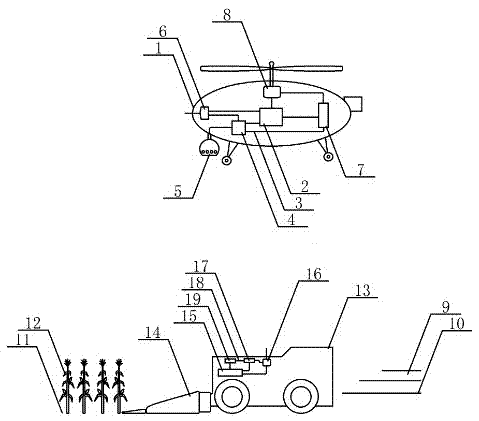
[0025] The drone flies in the low air above the unmanned corn harvester that harvests the corn. The photoelectric pod is installed under the front of the drone. The 37 million pixel CCD camera installed in the photoelectric pod is aimed at the corn field. The unmanned corn harvester and the corn harvested grain field and the unharvested corn grain field perform fully automated photography work. The image sensor in the CCD camera inputs the obtained aerial image information of the grain field into the electronic computer A for storage and imaging, and digital image input The flight control machine guides the flight of the drone. The aerial image information of the grain field is input into the electronic computer B through the wireless communication device A in the drone, radio waves and the wireless communication device B in the unmanned corn harvester for storage and calculation. The calculation result is input to the unmanned automatic driving device, and the control is not co...

Embodiment 2

[0027] The drone flies in the low air above the unmanned corn harvester that harvests corn. A photoelectric pod is installed under the front of the drone. The 41 million pixel CMOS camera installed in the photoelectric pod is aimed at the corn field. The unmanned corn harvester and the corn harvested grain field and the unharvested corn grain field perform fully automated photography work. The image sensor in the CMOS camera inputs the obtained aerial image information of the grain field into the electronic computer A for storage and imaging, and digital image input The flight control machine guides the flight of the drone. The aerial image information of the grain field is input into the electronic computer B through the wireless communication device A in the drone, radio waves and the wireless communication device B in the unmanned corn harvester for storage and calculation. The calculation result is input to the unmanned automatic driving device, and the control is not contro...


PUM


Abstract

The invention relates to an unmanned corn harvester, and belongs to the technical field of unmanned aerial vehicle application. An unmanned aerial vehicle flies in low altitude over the unmanned corn harvester which performs corn harvesting operation, the lower face of the front portion of the unmanned aerial vehicle is provided with an electro-optical pod, a high-pixel digital camera installed in the electro-optical pod performs full-automatic photography work by aiming at the corn harvester which harvests corn and surrounding corn field, an image sensor of the digital camera inputs acquired aerial image information of grain field into a first electronic computer to be stored and imaged, and a digital image is input into a flight control computer to guide flying of the unmanned aerial vehicle. The aerial image information of the grain field is input into a second electronic computer through a first wireless communication device in the unmanned aerial vehicle, radio waves and a second wireless communication device in the unmanned corn harvester to be stored and calculated, and a calculated result is input into an unmanned self-control driving device to control a corn harvesting table arranged on the front portion of the unmanned corn harvester to perform operation of harvesting the corn.

Description


Claims


Application Information

Patent Timeline
Owner WUXI TONGCHUN NEW ENERGY TECH
Why Eureka
Try Eureka