Polishing device and method for groove bottom

A technology of polishing device and polishing sheet, which is applied in the direction of grinding/polishing equipment, grinding/polishing hand tools, metal processing equipment, etc., can solve problems such as sealing strip falling off, surface flatness defects, etc., to reduce width difference, reduce The difference in surface flatness, the effect of reducing the probability of partial peeling

Active Publication Date: 2016-03-30
KONFOONG MATERIALS INTERNATIONAL CO LTD
View PDF5 Cites 2 Cited by
  • Summary
  • Abstract
  • Description
  • Claims
  • Application Information

AI Technical Summary

Problems solved by technology

[0006] However, in practice, after the sandpaper polishing process at the bottom of the groove 11, even if the flatness of the bottom surface of the groove 11 is improved, after

Method used


Image

  • Polishing device and method for groove bottom
  • Polishing device and method for groove bottom
  • Polishing device and method for groove bottom

Examples


Embodiment 1

[0038] refer to Figure 2 to Figure 4 , which shows a schematic diagram of an embodiment of the groove bottom polishing device of the present invention.

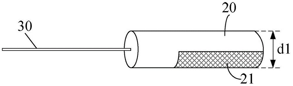
[0039] refer to figure 2 , The groove bottom polishing device provided in this embodiment includes: a cleaning head 20 , and a polishing sheet 21 mounted on the cleaning head 20 .

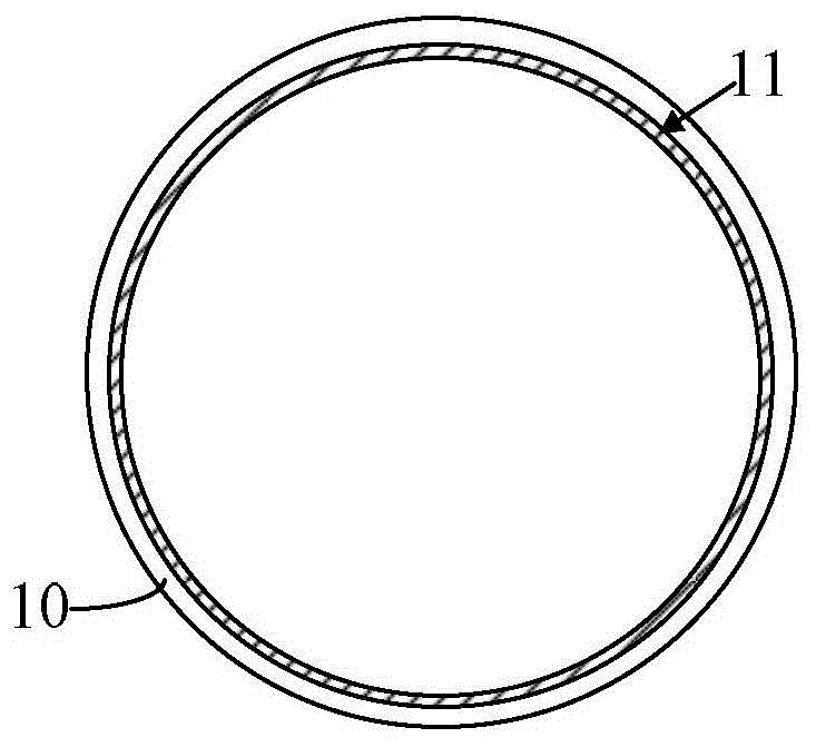
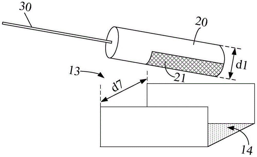
[0040] refer to image 3 , during the polishing process of the bottom 14 of the groove 13 on the back of the target backplate, the cleaning head 20 is embedded in the groove 13, and the polishing sheet 21 is attached to the bottom 14 of the groove 13 to clean the The bottom 14 of the groove 13 is polished to remove defects such as raised particles on the bottom 14 and improve the flatness of the bottom 14 of the groove 13 .

[0041] In this embodiment, the cleaning head 20 is a columnar structure, further optionally, the cleaning head 20 is a cylindrical structure, and the polishing sheet 21 is attached to the side wall of the cylindrical cle...

Embodiment 2

[0057] refer to Figure 5 and Figure 6 Shown is a schematic structural view of a groove bottom polishing device according to another embodiment of the present invention.

[0058] The similarities between the groove bottom polishing device in this embodiment and the groove bottom polishing device in Embodiment 1 will not be repeated, and the differences are:

[0059] In this embodiment, the cleaning head 40 is in the shape of a cubic column, and the polishing sheet 41 is attached to a side wall surface of the cubic column, and has a flat planar structure. Moreover, the width d5 ​​of the polishing sheet 41 is smaller than the width of the bottom surface of the groove.

[0060] In this embodiment, the width d2 of the cleaning head 40 is larger than the width of the groove, so that after the cleaning head is embedded in the groove, the side wall of the cleaning head 40 is against the side wall of the groove to enhance polishing. Sheet 41 is positioned.

[0061] In this embodi...


PUM


Abstract

The invention provides a polishing device and method for a groove bottom. The polishing device for a groove bottom comprises: a cleaning head and a polishing sheet which is installed on the cleaning head and whose width is less than that of the groove. When the device is being used, the cleaning head is placed in the groove and the polishing sheet is in touch with the bottom of the groove. During the process of groove bottom polishing, because the width of the polishing sheet is less than that of the groove bottom, the problem of the groove being broadened due to partial damage to a groove sidewall caused by attrition between the polishing sheet and the groove sidewall is avoided and then the incidence that different parts of the groove have different widths is reduced; the difference of surface roughness of different parts of sealing strips caused by the sealing strips being inserted in the groove having partial width difference is reduced; thus the shedding probability of partial sealing strips is reduced.

Description

technical field [0001] The invention relates to the field of sputtering target manufacturing, in particular to a groove bottom polishing device and method. Background technique [0002] The target assembly used in the magnetron sputtering coating process consists of a target and a back plate. During use, fix the back plate on the sputtering device, and bombard the front of the target with various high-energy ions to sputter out neutral target atoms or molecules, which are deposited on the substrate to form a thin film. [0003] In the magnetron sputtering coating process, the magnetron sputtering coating process is 10 -9 It is carried out in a high-vacuum environment of Pa, and the target is in a high-voltage electric field and a magnetic field as high as 300°C to 500°C. In order to avoid the sharp rise of the target temperature under high vacuum and high temperature conditions, during the magnetron sputtering coating process, methods such as spraying high-pressure cooling...

Claims


Application Information

Patent Timeline
IPC IPC(8): B24D15/02
Inventor 姚力军相原俊夫大岩一彦潘杰王学泽钟伟攀
Owner KONFOONG MATERIALS INTERNATIONAL CO LTD
Why Eureka
Try Eureka