Check patentability & draft patents in minutes with Patsnap Eureka AI!

Inkjet head and printer

An inkjet head and ink technology, used in printing, inking devices, etc., can solve the problems of many parts boundary surfaces, ink intrusion into the inside of the cover and adhesion, etc.

Active Publication Date: 2017-04-12
KK TOSHIBA +1
View PDF6 Cites 0 Cited by
  • Summary
  • Abstract
  • Description
  • Claims
  • Application Information

AI Technical Summary

Problems solved by technology

[0003] However, due to the complex shape of each part, there are many boundaries between parts, so when the ink tube is used to connect the pipe of the ink circulation system and the inkjet head, sometimes the ink overflows from the pipe, and the ink invades the inside of the cap and adheres to the printing surface. Wiring substrate

Method used


Image

  • Inkjet head and printer
  • Inkjet head and printer
  • Inkjet head and printer

Examples


Embodiment approach

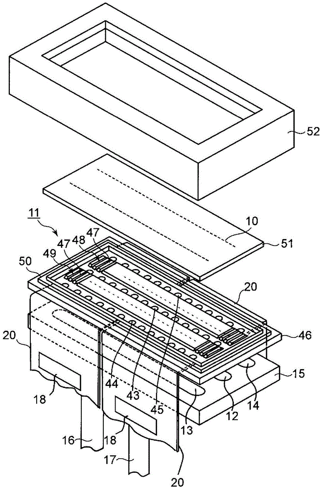
[0019] figure 1 It is an exploded perspective view of an inkjet head according to one embodiment. The inkjet head of this embodiment is provided with: a head body 11 having a plurality of discharge ports 10 for ink, a manifold 15 having an ink supply path 12 and ink discharge paths 13, 14 to the head body 11, and Connecting pipes 16 and 17 (pipes) communicating with the respective ink supply passages 12 and ink discharge passages 13 and 14 are provided at 15 in the pipe length direction perpendicular to the head body 11 .

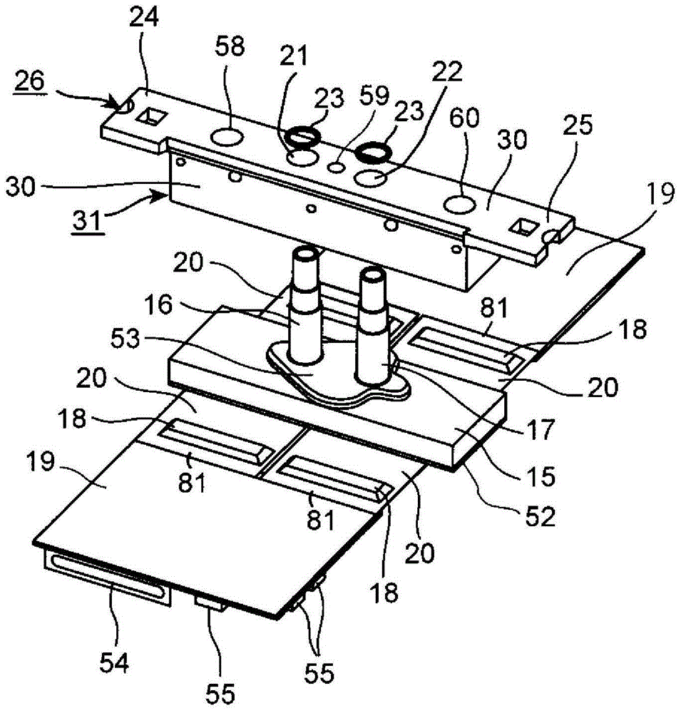
[0020] figure 2 is an exploded perspective view of part of an inkjet head according to an embodiment, and figure 1 The example of is displayed upside down. The symbols that have been described each represent the same element. The inkjet head of this embodiment is equipped with: four flexible substrates 20, which have a film (flexible) bent from a developed posture perpendicular to the tube longitudinal direction of each connecting tube 16, 17 to a curv...


PUM


Abstract

Inkjet heads and printers are provided to prevent ink from ingressing into the inside of the cover and attaching to the printed wiring substrate. In one embodiment, there is provided an inkjet head, which has: the head body; Multiple pipelines; Multiple flexible substrates; Reference board; Plate table; Plurality of inner covers, each having an inner surface covering the plate, a first mating face in contact with the side of the inner surface, an outer surface of the opposite side of the inner surface, and a second mating face formed on the outer surface side, using the flexible base plate bending posture configuration of the driving circuit on the second mating facial side using the flexible substrate; Plurality of side covers, together with these inner covers to dissipate heat and have an inner surface facing each outer surface, the inner surface side of the third mating face in contact with the second mating face, and the outer surface combined with the printed wiring substrate.

Description

technical field [0001] One embodiment relates to an inkjet head and a printer. Background technique [0002] An inkjet head is provided in the printer main body (inkjet printer main body), and ink is pressurized to discharge liquid droplets. Conventionally, a driver IC for ejection driving is provided in an inkjet head, and a cover is provided outside the driver IC to release heat from the driver IC as a heat sink (for example, refer to Patent Document 1). In addition, the printed wiring board on which the peripheral circuit for driving the driver IC is packaged is provided, and it is necessary to prevent the ink leaked from the interface between parts such as the head body, the cover plate, and the cover or the ink scattered in the form of mist from adhering to the printed wiring board. . Therefore, the intrusion of ink is prevented by pouring a sealing material such as an adhesive into the boundary surface between the parts to perform sealing. Boundary surfaces refer to...

Claims


Application Information

Patent Timeline
Patent Type & Authority Patents(China)
IPC IPC(8): B41J2/01B41J2/17B41J2/165
CPCB41J2/155B41J2002/14491B41J2202/19B41J2202/20B41J2/2146B41J2/17513B41J2/1752B41J2/17523B41J2/17553B41J2002/14362B41J2/1433B41J2/14201B41J2002/14419
Inventor 饭岛知实
Owner KK TOSHIBA
Features
  • R&D
  • Intellectual Property
  • Life Sciences
  • Materials
  • Tech Scout
  • Unparalleled Data Quality
  • Higher Quality Content
  • 60% Fewer Hallucinations
Learn More