
Inner cage conveying mechanical hand

A manipulator and inner cage technology, applied in manipulators, program-controlled manipulators, removal of liquid/gas/vapor by centrifugal force, etc., can solve the problems of complex manipulator structure, inability to apply fabric centrifugal dehydration system, etc., and achieve the effect of simple structure

Active Publication Date: 2016-04-06
GAOWANLI TECH ZHONGSHAN CO LTD
View PDF3 Cites 9 Cited by
  • Summary
  • Abstract
  • Description
  • Claims
  • Application Information

AI Technical Summary

Problems solved by technology

[0003] In order to solve the problem that the existing manipulator has a complex structure and cannot be applied to the fabric centrifugal dehydration system to clamp and transport the inner cage, the embodiment of the present invention provides an inner cage conveying manipulator

Method used


Image

  • Inner cage conveying mechanical hand
  • Inner cage conveying mechanical hand
  • Inner cage conveying mechanical hand

Examples


Embodiment Construction

[0032] In order to make the technical problems, technical solutions and beneficial effects solved by the present invention clearer, the present invention will be further described in detail below in conjunction with the accompanying drawings and embodiments. It should be understood that the specific embodiments described here are only used to explain the present invention, not to limit the present invention.

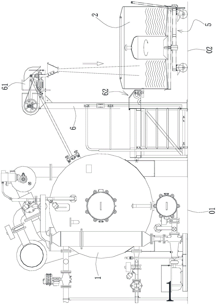
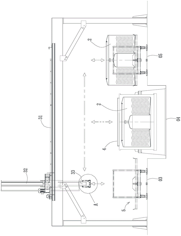
[0033] Such as figure 1 , figure 2 As shown, a fabric automatic dyeing and dehydration system is set along the production line. The production line is sequentially equipped with dyeing station 01, fabric joining station 02, dehydration station 03, centrifugal dehydration station 04 and post-processing station 05. The system at least includes: dyeing equipment 1, an inner cage 2, a manipulator 3, and a centrifuge 4, and the centrifuge 4 is fixedly installed in the centrifugal dehydration station 04;

[0034] The dyeing equipment 1 is located at the dyeing station 01 an...


PUM


Abstract

The embodiment of the invention discloses an inner cage conveying mechanical hand. A connecting piece is arranged on an inner cage. The inner cage conveying mechanical hand is characterized by comprising a transverse guide rail, a longitudinal movement arm, and a clamping device arranged at the lower end of the longitudinal movement arm. The whole longitudinal movement arm can horizontally move leftwards and rightwards relative to the transverse guide rail. The longitudinal movement arm can drive the clamping device to move up and down. The clamping device comprises a body connected with the lower end of the longitudinal movement arm, a clamping head arranged at the lower end of the body and a clamping jaw pivoted to the clamping head. The clamping jaw can rotate relative to the clamping head so as to clamp or loosen the connecting piece on the inner cage. According to the inner cage conveying mechanism hand, the whole longitudinal movement arm can horizontally move leftwards and rightwards relative to the transverse guide rail, the longitudinal movement arm can drive the clamping device to move up and down, the clamping jaw of the clamping device can rotate relative to the clamping head to clamp or loosen the connecting piece of the inner cage, the structure is simple, and the inner cage conveying mechanical hand can be applied to a fabric centrifugal dewatering system to achieve inner cage clamping and conveying.

Description

Technical field: [0001] The invention relates to a manipulator for conveying an inner cage, in particular to a manipulator used in a fabric centrifugal dehydration system in the textile manufacturing industry for clamping and conveying an inner cage. Background technique: [0002] The existing manipulator has a complex structure and cannot be applied to the fabric centrifugal dehydration system to clamp and transport the inner cage. Invention content: [0003] In order to solve the problem that the existing manipulator has a complicated structure and cannot be applied to the fabric centrifugal dehydration system to clamp and transport the inner basket, an embodiment of the present invention provides an inner basket conveying manipulator. [0004] A kind of inner cage conveying manipulator, described inner cage is provided with connector, it is characterized in that, this manipulator comprises transverse guide rail, longitudinally moving arm, and the clamping device that is...

Claims


Application Information

Patent Timeline
Patent Type & Authority Applications(China)
IPC IPC(8): D06B15/10D06B23/04B25J9/02B25J15/08
CPCB25J9/02B25J15/08D06B15/10D06B23/04
Inventor 云天皓
Owner GAOWANLI TECH ZHONGSHAN CO LTD
Learn More