
Masonry wall movement joint fireproof and heat-preserving structure and installation method thereof

A deformation joint and masonry wall technology, applied in the directions of thermal insulation, fire prevention, building structure, etc., can solve the problems of single functional requirements, loss of thermal insulation effect, and single deformation form adaptable to deformation joint structure, so as to achieve a wide range of adaptability and meet construction requirements. Requirements, the effect of easy installation

Inactive Publication Date: 2016-04-06
SHANDONG UNIV OF SCI & TECH +1
View PDF0 Cites 1 Cited by
  • Summary
  • Abstract
  • Description
  • Claims
  • Application Information

AI Technical Summary

Problems solved by technology

At the same time, after the wall is disconnected, the inside of the building and the outside of the building are connected, and the insulation effect of the building wall is lost at this part, which affects the overall insulation effect of the building.
[0003] Some measures have been taken in the prior art to solve the above problems, but there are mainly the following problems: 1. The wall function requirements that the deformation joint structure can meet are relatively simple, either only have the function of fire prevention, or only have the function of heat preservation; 2. The structure of the deformation joint The form of adapting to the deformation is relatively simple, often only adapting to the expansion and contraction deformation, and cannot adapt to the settlement deformation

Method used


Image

  • Masonry wall movement joint fireproof and heat-preserving structure and installation method thereof
  • Masonry wall movement joint fireproof and heat-preserving structure and installation method thereof
  • Masonry wall movement joint fireproof and heat-preserving structure and installation method thereof

Examples


Embodiment Construction

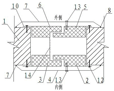
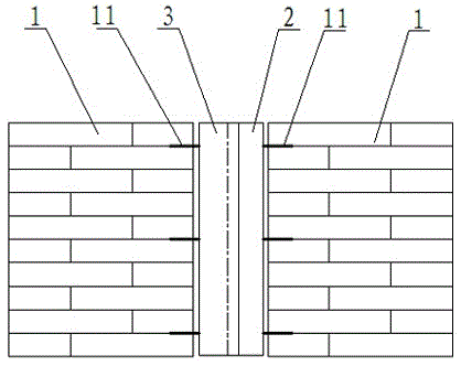
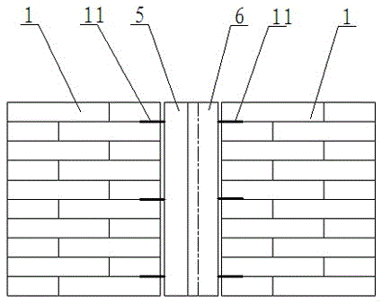
[0031] According to the accompanying drawings, a fire-proof and heat-preservation structure for deformation joints of masonry walls, an L-shaped fire-proof inner panel 2 and an L-shaped fire-proof outer panel 3 are arranged on the inner side of the wall, and the fire-proof inner panel 2 and the fire-proof outer panel 3 are connected to the wall through the tail 1. The base layer is connected and fixed, and a groove-shaped fireproof cover 4 is also provided on the inner surface of the wall 1. The fireproof cover 4 is fixed to the fireproof inner panel 2 by bolts 13. An L-shaped thermal insulation inner panel 5 and an L-shaped thermal insulation outer panel 6 are arranged on the outside of the wall. Both the thermal insulation inner panel 5 and the thermal insulation outer panel 6 are connected to the base layer of the wall 1 through tail fins. Cover plate 7, insulation cover plate 7 is fixed with insulation inner plate 5 by bolt 13. A tension spring 14 is arranged between the f...


PUM


Abstract

The invention provides a masonry wall movement joint fireproof and heat-preserving structure. An L-shaped fireproof inner plate and an L-shaped fireproof outer plate are arranged on the inner side of a wall and are fixedly connected to a base layer of the wall through tail wings. A slot type fireproof cover plate is further arranged on the surface of the inner side of the wall and is fixed to the fireproof inner plate through bolts. An L-shaped heat-preserving inner plate and an L-shaped heat-preserving outer plate are arranged on the outer side of the wall and are connected with the base layer of the wall through tail wings. A heat-preserving cover plate is further arranged on the surface of the outer side of the wall and is fixed to the heat-preserving inner plate through bolts. A torsion spring is arranged between the fireproof outer plate and the heat-preserving outer plate. Tongue-and-groove portions of the fireproof outer plate and the fireproof inner plate can be attached through tension of the torsion spring, and tongue-and-groove portions of the heat-preserving outer plate and the heat-preserving inner plate can be attached. Whether telescopic deformation or settlement deformation happens, the fireproof outer plate and the fireproof inner plate will not be separated from each other, and the heat-preserving outer plate and the heat-preserving inner plate will not be separated from each other.

Description

technical field [0001] The invention belongs to the construction field of deformation joints of buildings, in particular to a fire prevention and heat preservation structure of deformation joints of masonry walls and an installation method thereof. Background technique [0002] Building deformation joints are gaps set up by buildings to resist damage caused by temperature, subsidence, earthquakes, etc., but after setting deformation joints, the building is artificially divided into multiple monomers. The foundation, wall, floor, roof and other parts of the building have been disconnected. After the main components in the building are disconnected, when a fire breaks out inside the building, the deformation joints in the building wall will easily become the way for the fire to spread, posing a great threat to the buildings above the fire point. At the same time, after the wall is disconnected, the inside of the building is connected to the outside of the building, and the th...

Claims


Application Information

Patent Timeline
Patent Type & Authority Applications(China)
IPC IPC(8): E04B1/68E04B2/02E04B1/76E04B1/94
CPCE04B1/68E04B1/76E04B1/94E04B2/02
Inventor 尹发利候新平类兴财
Owner SHANDONG UNIV OF SCI & TECH
Learn More