Fastening type screw spike

A screw and fastening technology, which is applied in the field of mechanical parts, can solve the problems of hard knocking, easy deformation of the nail cap, and poor fastening effect, so as to avoid loosening

Inactive Publication Date: 2016-04-06
QIDONG HUITONG SCREW FACTORY
View PDF0 Cites 1 Cited by
  • Summary
  • Abstract
  • Description
  • Claims
  • Application Information

AI Technical Summary

Problems solved by technology

When using fastening screws with this structure, it is laborious to drive in, the cap is easily deformed, and the fastening effect is not good

Method used


Image

  • Fastening type screw spike

Examples


Embodiment Construction

[0010] The implementation of the present invention will be illustrated by specific specific examples below, and those skilled in the art can easily understand other advantages and effects of the present invention from the contents disclosed in this specification.

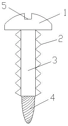
[0011] Such as figure 1 Shown is a structural diagram of the present invention, a fastening screw, including a nut 1, a screw 3 and a screw 4, one end of the screw 3 is fixedly connected to the nut 1, and the other end of the screw 3 is fixedly connected to the screw 4 ; The top of the nut 1 offers a groove 5, the structure of the groove 5 is a cross.

[0012] Both sides of the screw rod 3 are provided with screw teeth 2, the screw teeth 2 are evenly arranged along the vertical direction of the screw rod 3, the structure of the screw teeth 2 is a cone, and the cone height of the cone screw teeth 2 is 1-2mm. Screw teeth 2 are arranged on both sides of the screw rod 3, which can effectively avoid the loosening of the...


PUM


Abstract

The invention discloses a fastening type screw spike. The fastening type screw spike is characterized by comprising a nut, a screw and a bolt; one end of the screw is fixedly connected with the nut, and the other end of the screw is fixedly connected with the bolt; and a groove is formed in the top end of the nut, and the structure of the groove is in a cross shape. The fastening type screw spike has the advantages that spiral teeth are arranged on the two sides of the screw, the screw spike can be effectively prevented from loosening and the fastening effect can be further achieved.

Description

technical field [0001] The invention relates to the field of mechanical parts, in particular to a fastening screw. Background technique [0002] A screw, a class of sharp-ended, nail-like, threaded parts on small cylindrical or conical metal rods, having a grooved or dimpled head, used alone. [0003] An existing fastening screw has a nail cap, a nail body, and a nail tip, and arc-shaped threads are arranged around the nail body. When using fastening screws of this structure, it is laborious to drive in, the cap is easily deformed, and the fastening effect is not good. Contents of the invention [0004] The object of the present invention is to address the deficiencies of the prior art, and now provide a fastening screw that has a good fastening effect and can only be tightened but not loosened. [0005] In order to solve the above-mentioned technical problems, the technical solution adopted by the present invention is: a fastening screw, the innovation point of which is...

Claims


Application Information

Patent Timeline
Patent Type & Authority Applications(China)
IPC IPC(8): F16B35/04F16B39/282
CPCF16B35/048F16B39/282
Inventor 周兴
Owner QIDONG HUITONG SCREW FACTORY
Why Eureka
Try Eureka