Ceiling punch laser positioning apparatus

A positioning device and hole laser technology, which is used in measuring devices, instruments, mapping and navigation, etc., can solve problems such as troublesome positioning screw holes

Inactive Publication Date: 2016-04-06
任永斌
View PDF0 Cites 0 Cited by
  • Summary
  • Abstract
  • Description
  • Claims
  • Application Information

AI Technical Summary

Problems solved by technology

[0003] In order to overcome the troublesome shortcomings of positioning screw holes for installing equipment on the existing ceiling, the present invention proposes a laser positioning device for drilling holes in the ceiling to solve this problem. Easily realize the positioning of punching holes on the ceiling, and one person can easily complete it

Method used


Image

  • Ceiling punch laser positioning apparatus

Examples


Embodiment Construction

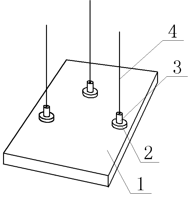
[0009] in figure 1 In the embodiment, we take the implementation of a ceiling drilling laser positioning device as an example to further illustrate the present invention:

[0010] figure 1 It is a schematic diagram of the structure of a ceiling drilling laser positioning device of the present invention. In the figure, the water platform 1 is a platform with a smooth surface. The length and width can be determined according to the specific situation. The surface can be made of flat iron plate. In order to reduce weight, The thickness of the iron plate can be thinner. The magnet 2 is a round magnet, as long as it can be firmly attached to the iron plate, but it needs to be flat on both sides. The laser transmitter 3 can be a point laser or a cross-hair laser, which is selected from the band It is more convenient to use a battery as a power source. Fix the laser transmitter 3 underneath the magnet 2 by bonding or other fixing methods. However, it is required that when the water pla...


PUM


Abstract

The invention relates to a ceiling punch laser positioning apparatus. The apparatus is composed of a horizontal table, magnets and laser emitters, the bottom surfaces of the laser emitters are provided with the magnets to form magnetic laser emitters, the magnetic laser emitters are arranged in corresponding positions of the horizontal table provided with an iron plate, laser beams are vertical to the plane of the horizontal table, and the magnetic laser emitters are arranged in corresponding positions of the horizontal table provided with the iron plate to realize convenient use in order to realize simultaneous positioning of a plurality of holes. The apparatus adopting the above scheme solves the disadvantage of very troublesome positioning of installing device threaded holes on a ceiling, and can be used in convenient positioning of ceiling installing device holes.

Description

Technical field [0001] The invention relates to a punching positioning device, in particular to a positioning device for installing equipment on a ceiling that needs to be punched. Background technique [0002] At present, to install lamps and other equipment on the ceiling, you must first drill holes on the ceiling. Punching involves the positioning of the holes. The general method of positioning is to place the equipment at the location to be installed, and then use a pencil or marker. Mark the hole positions of the equipment on the ceiling. If there are several holes, mark a few places. Another method is to measure the distance between the equipment holes, and then use a ruler to measure the hole positions on the ceiling. When the hole positions are set, use impact Drill holes in the holes, then put the expansion screws in, and then fix the equipment on the ceiling with the screws. This process is completed. Since the positioning and drilling on the ceiling is a high-level ope...

Claims


Application Information

Patent Timeline
IPC IPC(8): G01C15/00
Inventor 任永斌
Owner 任永斌
Why Eureka
Try Eureka