Electrical device

A technology of electronic equipment and projectors, applied in instruments, projection devices, optics, etc., can solve problems such as inconvenient adjustment of projectors, and achieve the effect of improving user experience

Active Publication Date: 2016-04-06
LENOVO (BEIJING) LTD
View PDF5 Cites 2 Cited by
  • Summary
  • Abstract
  • Description
  • Claims
  • Application Information

AI Technical Summary

Problems solved by technology

[0004] In view of this, the present invention expects to provide an electronic device, which can at least solve the problem of inconvenient adjustment of the projector in the prior art, and improve user experience

Method used


Image

  • Electrical device
  • Electrical device
  • Electrical device

Examples


Embodiment 1

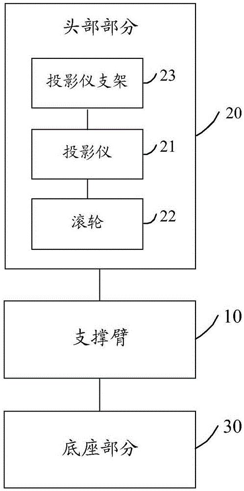
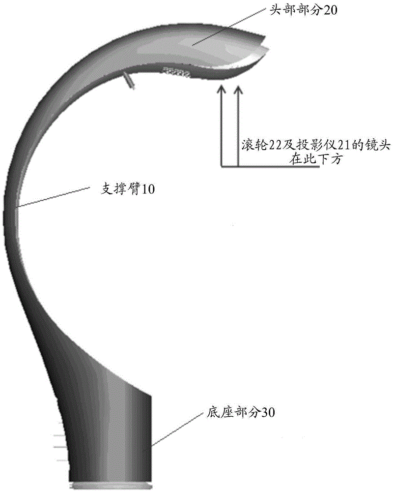
[0038] The invention provides an electronic device, figure 1 A schematic diagram of the composition structure of an electronic device provided by an embodiment of the present invention, the electronic device includes: a support arm 10, a head part 20 connected to the other end of the support arm, a head part 20 connected to one end of the support arm Base portion 30; wherein, as figure 1 As shown, the head portion 20 includes:

[0039] The projector 21 is fixed to the head part 20 through a projector bracket 23, at least for projecting to the first area of ​​the plane where the base part 30 is placed;

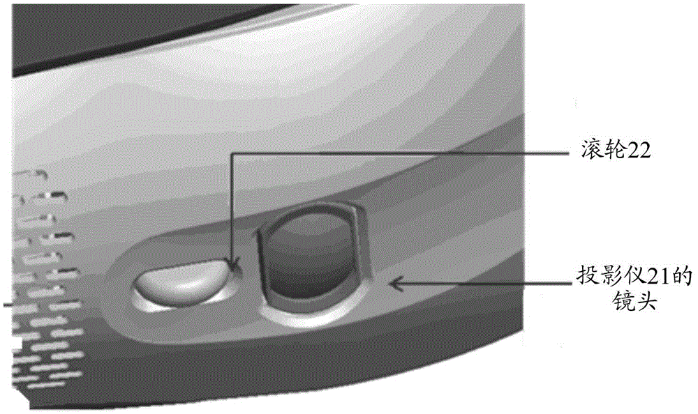
[0040] The roller 22 is connected with the projector 21 and is used for adjusting the image projected by the projector 21 .

[0041] Here, adjusting the image projected by the projector 21 mainly refers to adjusting the definition of the image.

[0042] Preferably, the projector bracket 23 can be fixed on the shell of the head portion 20 by fasteners. For example, the faste...

Embodiment 2

[0056] The invention provides an electronic device, Figure 5 A schematic diagram of the composition structure of another electronic device provided by an embodiment of the present invention, the electronic device includes: a support arm 10, a head part 20 connected to the other end of the support arm 10, and a head part 20 connected to the support arm 10 A base part 30 connected at one end; wherein, as Figure 5 As shown, the head portion 20 includes:

[0057] The projector 21 is fixed to the head part 20 through a projector bracket 23, at least for projecting to the first area of ​​the plane where the base part 30 is placed;

[0058] The roller 22 is connected with the projector 21 and is used for adjusting the image projected by the projector 21 .

[0059] Preferably, the projector bracket 23 can be fixed on the shell of the head portion 20 by fasteners. For example, the fasteners may be bolts and nuts, or screws, or screws, or studs, or rivets, and the like.

[0060] P...

Embodiment 3

[0070] The invention provides an electronic device, Figure 6 A schematic diagram of the composition structure of another electronic device provided by an embodiment of the present invention, the electronic device includes: a support arm 10, a head part 20 connected to the other end of the support arm 10, and a head part 20 connected to the support arm 10 A base part 30 connected at one end; wherein, as Figure 6 As shown, the head portion 20 includes:

[0071] The projector 21 is fixed to the head part 20 through a projector bracket 23, at least for projecting to the first area of ​​the plane where the base part 30 is placed;

[0072] The roller 22 is connected with the projector 21 and is used to adjust the image projected by the projector 21;

[0073] Slider 24, one end is connected with knob extension rod 25, and the other end is connected with roller 22, can slide along fixed bracket 26;

[0074] One end of the knob extension rod 25 is connected with the slider 24 , an...


PUM


Abstract

The present invention discloses an electrical device. The electrical device comprises: a supporting arm, a base portion connected to one end of the supporting arm, and a head portion connected to the other end of the supporting arm, wherein the head portion comprises a projector which is fixed to the head portion by a projector bracket and is at least used for carrying out projection on a first region of a placed plane of the base portion, and a roller which is connected with the projector and is used to adjust an image projected by the projector; and a first portion of the roller is exposed on a first outer surface of a housing of the head portion. By applying the technical scheme of the present invention, at least the problem of inconvenience for adjusting the projector in the prior art can be solved, and the usage experience of a user is promoted.

Description

technical field [0001] The present invention relates to the field of terminal equipment, in particular to an electronic equipment. Background technique [0002] With the development of electronic technology, the application range of projectors is becoming wider and wider, and it has been widely used in fields such as homes, offices, schools, and entertainment venues. [0003] At present, there are many ways to install the projector, such as desktop placement, hoisting, bracket placement and so on. However, in some cases, such as a projector mounted under a ceiling, it is not easy to adjust it when it is installed at a higher position, for example, it is inconvenient to adjust a projector installed on the ceiling of a classroom. Contents of the invention [0004] In view of this, the present invention expects to provide an electronic device, which can at least solve the problem of inconvenient adjustment of the projector in the prior art, and improve user experience. [0...

Claims


Application Information

Patent Timeline
Patent Type & Authority Applications(China)
IPC IPC(8): G03B21/14
CPCG03B21/142G03B21/145
Inventor 徐玉龙
Owner LENOVO (BEIJING) LTD
Why Eureka
Try Eureka