
Display panel scan driving method

A scanning drive and display panel technology, applied in the field of scan drive, can solve problems such as cost reduction and shortage

Inactive Publication Date: 2016-04-06
TCL CHINA STAR OPTOELECTRONICS TECH CO LTD
View PDF11 Cites 6 Cited by
  • Summary
  • Abstract
  • Description
  • Claims
  • Application Information

AI Technical Summary

Problems solved by technology

Nevertheless, the scan driving circuit in the prior art still lacks a solution that can effectively reduce costs and improve quality, and can be applicable to 2D / 3D display at the same time

Method used


Image

  • Display panel scan driving method
  • Display panel scan driving method
  • Display panel scan driving method

Examples


Embodiment Construction

[0020] In order to make the above objects, features and advantages of the present invention more comprehensible, preferred embodiments of the present invention are exemplified below and described in detail in conjunction with the accompanying drawings. Furthermore, the directional terms mentioned in the present invention, such as "up", "down", "front", "back", "left", "right", "inside", "outside", "side", etc., It is only for orientation with reference to the attached drawings. Therefore, the directional terms used are used to illustrate and understand the present invention, but not to limit the present invention.

[0021] GOA (gate on array) technology is a common method in the industry that can effectively reduce manufacturing costs. It is mainly to directly fabricate the scan drive circuit on the array substrate, that is, to pass the function of the gate drive chip through TFT-LCD (Thin Film Transistor Liquid Crystal Display) The manufacturing process is realized on the gl...


PUM


Abstract

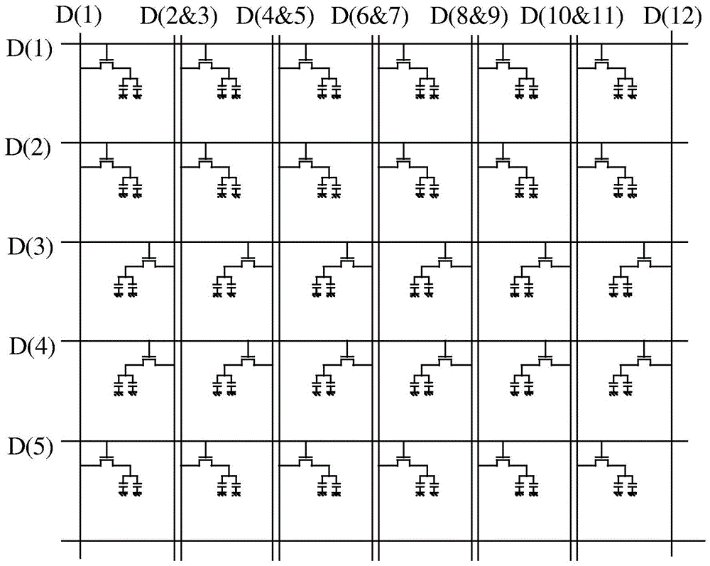
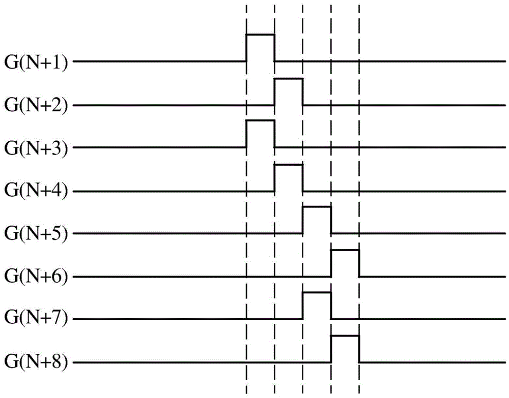
The invention discloses a display panel scan driving method, which is characterized in that the display panel comprises a pixel driving circuit. The pixel driving circuit comprises n pieces scan lines and m pieces of data lines; the scan lines and the data lines are interlaced to define several pixel units; the scan driving method comprises the steps of unlatching an Xth scanning line through a clock signal no more than 45% duty ratio, and unlatching a (X+2)th scanning line at the same time, wherein, X is an integer, and 1<=X<=n-2.

Description

【Technical field】 [0001] The present invention relates to the field of liquid crystal display, in particular to a scanning driving method of a display panel. 【Background technique】 [0002] Nowadays, in the liquid crystal display industry, reducing costs and improving quality are the keys to improving the competitiveness of liquid crystal panel manufacturers. Secondly, in order to meet market demand, the resolution and penetration rate of large-size panels are required to be increased, so that the opening time of each scanning line is shortened, which will inevitably lead to insufficient charging of pixels. Insufficient charging will, on the one hand, lead to a decrease in panel transmittance, and increase the brightness of the backlight to maintain the same display brightness, which will increase the cost of the backlight module; on the other hand, insufficient charging will also affect the display effect of low-gray-scale images , making it more prone to the mura phenomen...

Claims


Application Information

Patent Timeline
Patent Type & Authority Applications(China)
IPC IPC(8): G09G3/36
CPCG09G3/3611G09G3/3648G09G2310/0205G02F1/13454G02F1/136286G02F1/1368G09G3/3677G09G3/3688G09G2310/0202
Inventor 王笑笑
Owner TCL CHINA STAR OPTOELECTRONICS TECH CO LTD
Learn More