Supercharge Your Innovation With Domain-Expert AI Agents!

Headrest support structure

A technology for supporting structures and headrests, applied in the direction of headrests, special positions of vehicles, chairs, etc., can solve problems such as difficulty in assembling components, inability to pivot the headrest, difficulty in assembling the headrest support part 54, etc.

Active Publication Date: 2016-04-06
TOYOTA JIDOSHA KK +1
View PDF12 Cites 0 Cited by
  • Summary
  • Abstract
  • Description
  • Claims
  • Application Information

AI Technical Summary

Problems solved by technology

However, if the fitting of these headrest supports 54 is tight, the assembly of the headrest supports 54 into the bracket 51 may be difficult
[0006] Also, similar problems can occur when the head restraint is pivotally supported on the seat back, even if the head restraint does not act as a dynamic shock absorber
That is, if the position of the pivot center of the headrest ends up shifting due to assembly tolerances of the components, the headrest will not be able to pivot as desired
On the other hand, in order to suppress the position shift of the pivot center of the headrest, the fitting of the parts needs to be tight, but if the fitting is tight, the assembly of the parts may be difficult

Method used


Image

  • Headrest support structure
  • Headrest support structure
  • Headrest support structure

Examples


Embodiment Construction

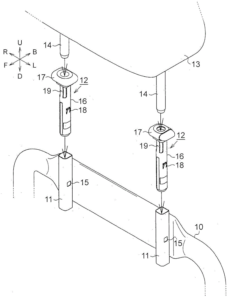
[0029] In the following, reference will be made to Figures 1 to 6 A first exemplary embodiment of the headrest support structure of the present invention will be described in detail. In the following description, the forward direction corresponding to the occupant sitting in the seat is referred to as "seat front F", the rearward direction corresponding to the occupant is referred to as "seat rear B", and the corresponding The direction to the left of the occupant is referred to as "seat left L", and the direction corresponding to the occupant's right is referred to as "seat right R". And, the direction in which one side of the headrest is positioned when viewed from the seat back is referred to as "seat upper U" or "upper U in the vertical direction of the seat", and the direction opposite to this direction is referred to as "D below the seat" or "D below in the vertical direction of the seat".

[0030] Such as figure 1 As shown, the headrest supporting structure of this...


PUM


Abstract

A headrest support (12) having a hollow cylindrical shape and into which a headrest stay (14) is inserted, is inserted into a bracket (11) that has a hollow cylindrical shape and is fixed to a seat back frame (10). A protrusion (19), a tip end of which is a pivot center of the headrest support (12), formed such that a protrusion amount thereof increases in response to insertion of the headrest stay (14), is provided on an outer peripheral surface of this headrest support (12).

Description

technical field [0001] The present invention relates to a headrest support structure that pivotally supports a headrest. Background technique [0002] A known headrest support structure uses the headrest as a dynamic shock absorber by elastically supporting the headrest pivotally on the seat back. For example, a support structure described in Japanese Utility Model Application Publication No. 61-149552 (JP61-149552U) is one such headrest support structure. [0003] Figure 7 is a view of the structure of the headrest support structure described in JP61-149552U. This headrest supporting structure has a bracket 51 fixed to a seat back frame 50 which is a frame member of the seat back. The bracket 51 is formed of a metal plate member bent into a substantially lateral U-shape. Through holes 52 and 53 are formed in the upper and lower portions of the bracket 51, respectively. A headrest support portion 54 made of resin and supporting a headrest stay is inserted into these thr...

Claims


Application Information

Patent Timeline
Patent Type & Authority Applications(China)
IPC IPC(8): B60N2/48
CPCB60N2205/20B60N2/812B60N2/80B60N2/809B60N2/897B60N2/894B60N2/826B60N2/832B60N2/68A47C7/36B60N2/7094B60N2/686B60N2/72B60N2/682A47C7/383
Inventor 高桥玄尾崎彰英
Owner TOYOTA JIDOSHA KK
Features
  • R&D
  • Intellectual Property
  • Life Sciences
  • Materials
  • Tech Scout
  • Unparalleled Data Quality
  • Higher Quality Content
  • 60% Fewer Hallucinations
Learn More