Power feed line switching circuit, branching device, submarine cable system, and power feed line switching method
A technology for feeder lines and switching circuits, which is applied to electromagnetic wave transmission systems, circuits, transmission systems, etc., and can solve problems such as checking feeder lines
Active Publication Date: 2016-04-06
NEC CORP
View PDF4 Cites 13 Cited by
- Summary
- Abstract
- Description
- Claims
- Application Information
AI Technical Summary
Problems solved by technology
[0009] In view of the above, an object of the present invention is to provide a feeder line switching circuit that solves the abov
Method used
View moreImage
Smart ImageViewing Examples
Examples
 PUM
 Abstract
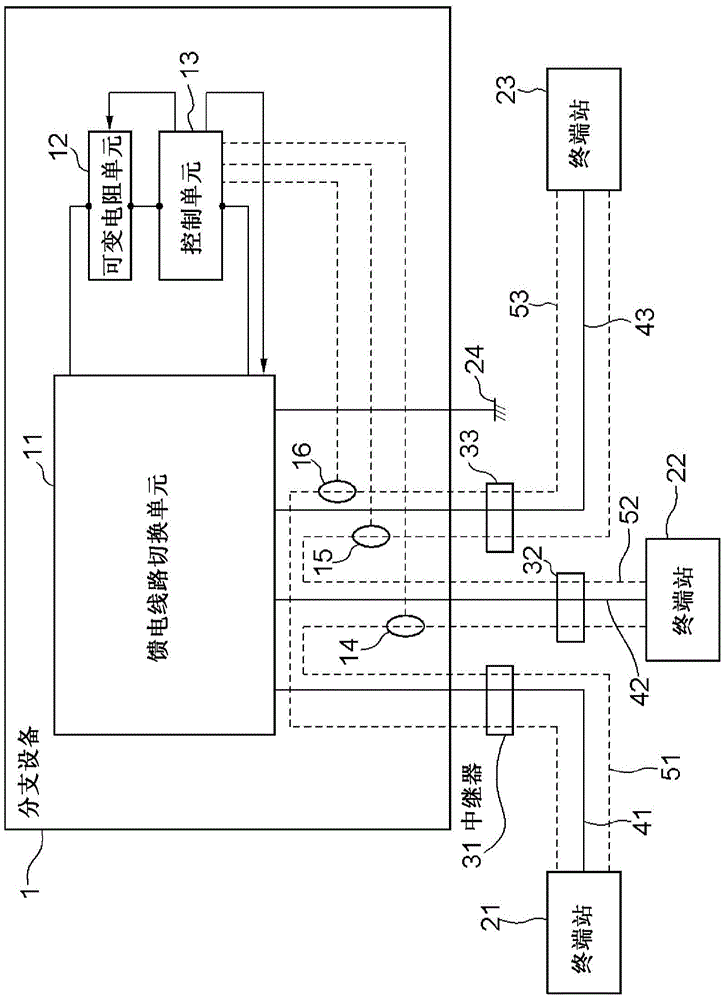
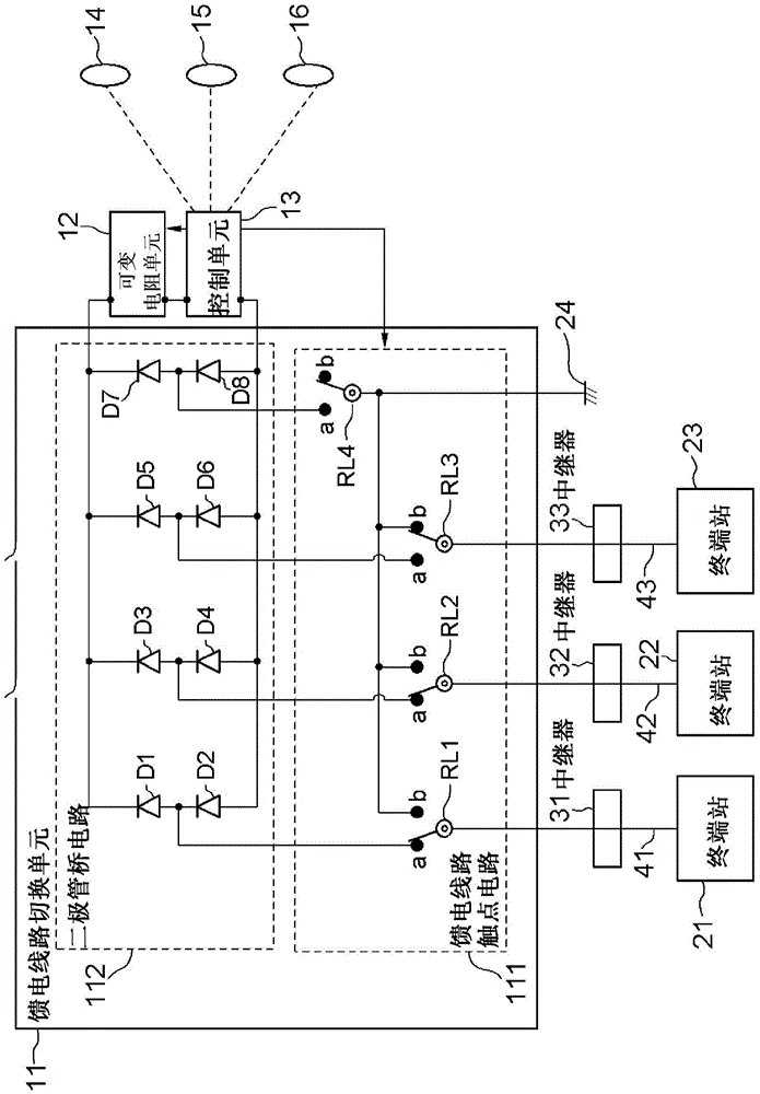
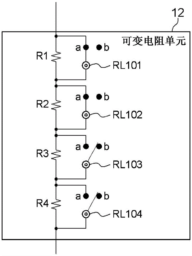
This power feed line switching circuit for switching connection states among a plurality of power feed lines has a plurality of switching circuits, and a variable resistance unit. The switching circuits switch the connection states among the power feed lines. The variable resistance unit is disposed on the connecting paths among the power feed lines before and after the switching, and the resistance values thereof change in conjunction with operations of the switching circuits.
Description
technical field [0001] The invention relates to a feeder circuit switching circuit, a branch device, a submarine cable system, and a feeder line switching method used in a submarine cable system. Background technique [0002] In submarine cable systems, arrangements are known to switch feeders when a fault occurs in any feeder for supplying a constant direct current to a repeater or branch reconfiguration) in order to reduce the area affected by failures (see, for example, Patent Document 1 [PTL1]). [0003] as in Figure 7 As explained in , the submarine cable system described in PTL1 is such that repeaters 74 to 76 are arranged between branch equipment 70 and each of terminal stations 71 to 73 . Furthermore, the branch device 70 and the terminal station devices 71 to 73 are connected by paths 77 to 79 and optical fibers 80 to 82 constituting feeder lines, respectively. In a state where no fault occurs in the paths 77 to 79, the paths 77 and 78 are connected through a fee...
Claims
Login to View More Application Information
Patent Timeline
 IPC IPC(8): H04B3/44
CPCH04B3/44H01H47/002H04B10/806H04B10/808
Inventor 间龙二
Owner NEC CORP
Features
- R&D
- Intellectual Property
- Life Sciences
- Materials
- Tech Scout
- Unparalleled Data Quality
- Higher Quality Content
- 60% Fewer Hallucinations
Learn More Browse by: Latest US Patents, China's latest patents, Technical Efficacy Thesaurus, Application Domain, Technology Topic, Popular Technical Reports.
© 2025 PatSnap. All rights reserved.Legal|Privacy policy|Modern Slavery Act Transparency Statement|Sitemap|About US| Contact US: help@patsnap.com


