Printed antenna structure

a technology of antenna structure and printed antenna, which is applied in the direction of antenna details, antennas, basic electric elements, etc., can solve the problems of limited local area network implementation, limited cabling, antenna modification, etc., and achieve the effect of reducing the size of the antenna

Inactive Publication Date: 2005-08-02
REALTEK SIMICONDUCTOR
View PDF4 Cites 113 Cited by
  • Summary
  • Abstract
  • Description
  • Claims
  • Application Information

AI Technical Summary

Benefits of technology

[0007]In view of these problems, it is the primary object of the present invention t...

Problems solved by technology

However, the implementation of local area network has been limited by its own nature.
The most visible example of the limitation is the cabling.
Since the space in a wireless n...

Method used


Image

  • Printed antenna structure
  • Printed antenna structure
  • Printed antenna structure

Examples


Embodiment Construction

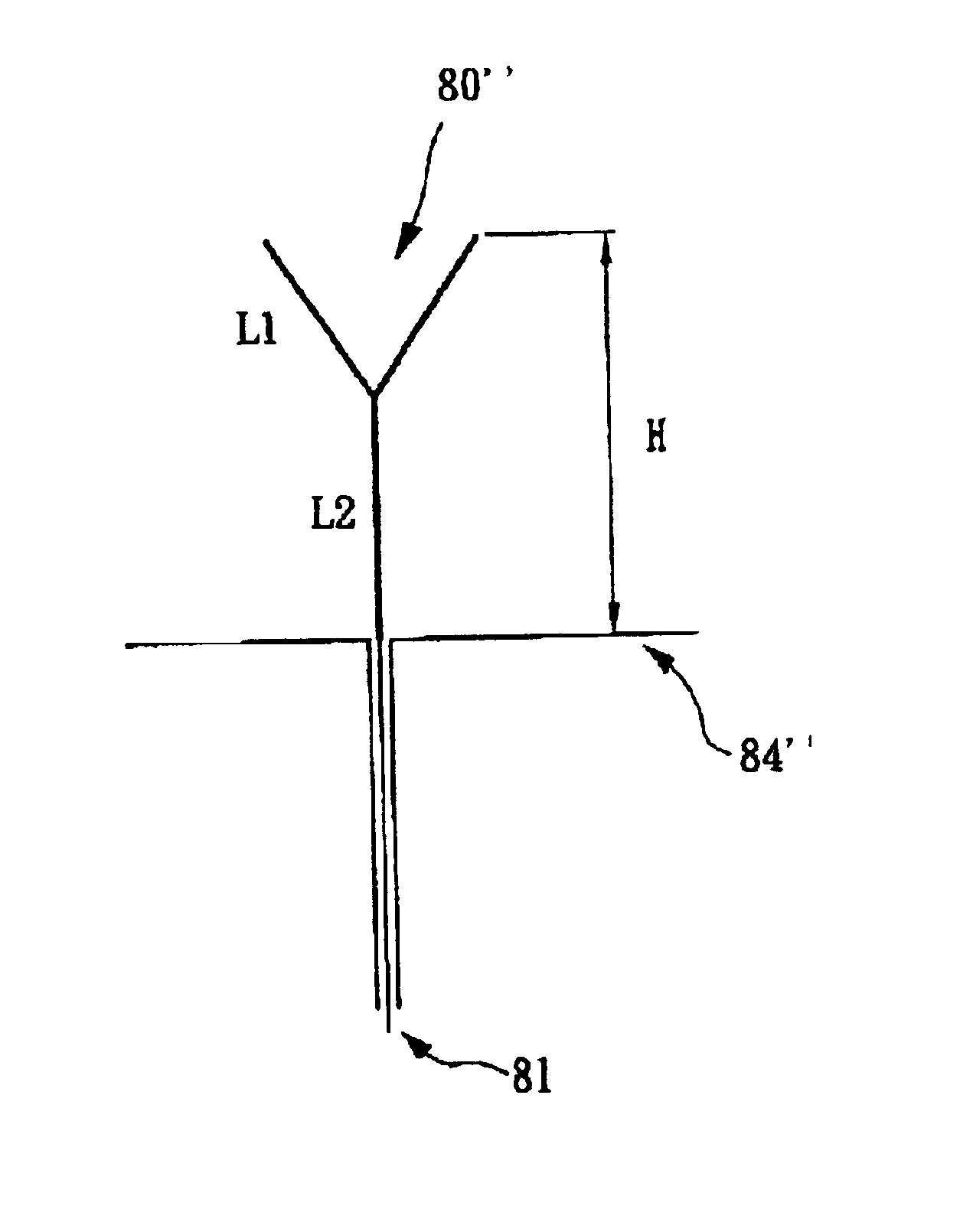
[0023]The present invention discloses a printed antenna with tuning element, which can be exemplified by the preferred embodiments as described hereinafter.

[0024]To a skilled in art, a dipole antenna having length of 2L can be regarded as the modification of an open transmission line having length of L. And the imaginary part (jXa) of the input impedance (Ra+jXa) of the dipole antenna is similar to the input impedance (jXt) of the open transmission line, wherein jXt=−jZ0 cot(2πL / λg), and Z0 is the characteristic impedance of the line. FIG. 4 is a diagram showing the relationship between the imaginary part Xt of the input impedance and the length L of an open transmission line. To satisfy the requirement of resonance (Xa≈Xt=0) for the antenna, the length L of the open transmission line should be one-fourth of the wavelength, that is, L=λg / 4. The following explains how the present invention works. FIG. 4 is a diagram showing the relationship between the imaginary part Xt of the input ...


PUM


Abstract

The present invention discloses a printed antenna structure. The printed antenna structure comprises: a dielectric layer having opposed surfaces, a ground plane layer covered on the first surface of the dielectric layer, a feed-line extending over the second surface of the dielectric layer and connecting to a driving circuitry, a primary radiating element connected to the feed-line and not extending over to the ground plane layer, and a tuning element connected to the primary radiating element and not extending over to the ground plane layer for adjusting the radiating frequency. The timing element her comprises two stubs each having a free end spaced apart from each other and a fixed end connected to the primary radiating element so as to reduce the overall length of the printed antenna.

Description

BACKGROUND OF THE INVENTION[0001]1. Field of the Invention[0002]The present invention generally relates to a printed antenna structure and, more particularly, to a printed antenna structure having a V-shaped tuning element.[0003]2. The Description of the Prior Art[0004]The rapid development of personal computer coupled with users desires to transmit data between personal computers has resulted in the rapid expansion of local area networks. Today, local area network has been widely implemented in many places such as in home, public access, and working place. However, the implementation of local area network has been limited by its own nature. The most visible example of the limitation is the cabling. One solution to this problem is to provide personal computer with a wireless network interface card to enable the personal computer to establish a wireless data communication link. Using a wireless network interface card, a personal computer, such like a notebook computer, can provide wi...

Claims


Application Information

Patent Timeline
IPC IPC(8): H01Q9/04H01Q1/38
CPCH01Q1/38H01Q9/0442
Inventor WU, MIN-CHUANKUO, PENG-YUANCHUNG, SHYH-JONGLEE, CHIH-MIN
Owner REALTEK SIMICONDUCTOR
Why Eureka
Try Eureka