Antenna structure with antenna radome and method for rising gain thereof

a technology of antenna radome and antenna structure, which is applied in the direction of radiating element structure, resonant antenna, protective material radiating elements, etc., can solve the problems of large antenna area, difficult to build disk antenna, and extremely high directional gain of disk antenna, so as to increase the size of the antenna structure can be greatly reduced, and the gain of the antenna structure is increased.

Active Publication Date: 2008-06-05
IND TECH RES INST
View PDF2 Cites 27 Cited by
  • Summary
  • Abstract
  • Description
  • Claims
  • Application Information

AI Technical Summary

Benefits of technology

[0009]It is therefore an object of the invention to provide an antenna structure with an antenna radome and a method of raising a gain thereof. A dielectric layer formed with metal patterns is utilized such that the antenna radome made of a metamaterial may be placed in a near-field zone of the radiating field of the antenna structure. Thus, the beamwidth of the radiating beams of the antenna structure can be converged to increase the gain of the antenna structure and the size of the antenna structure can be greatly reduced.

Problems solved by technology

The disk antenna has an extremely high directional gain, but an extremely large size.
So, it is difficult to build the disk antenna, and the disk antenna tends to be influenced by the external climate.
When the required directional gain of the array antenna increases, the number of array elements grows with a multiplier, the antenna area greatly increases, and the material cost also increases greatly.
Meanwhile, the feeding network, which is one of the important elements constituting the antenna array, becomes complicated severely.
Thus, the problems of phase precision and transmitted energy consumption occur such that the antenna gain cannot increase with the increase of the number of array elements.
Meanwhile, the multi-layer metal grid acts on the far-field of the antenna radiating field, so the overall size of the antenna structure increases and the utility thereof is restricted.

Method used


Image

  • Antenna structure with antenna radome and method for rising gain thereof
  • Antenna structure with antenna radome and method for rising gain thereof
  • Antenna structure with antenna radome and method for rising gain thereof

Examples


Embodiment Construction

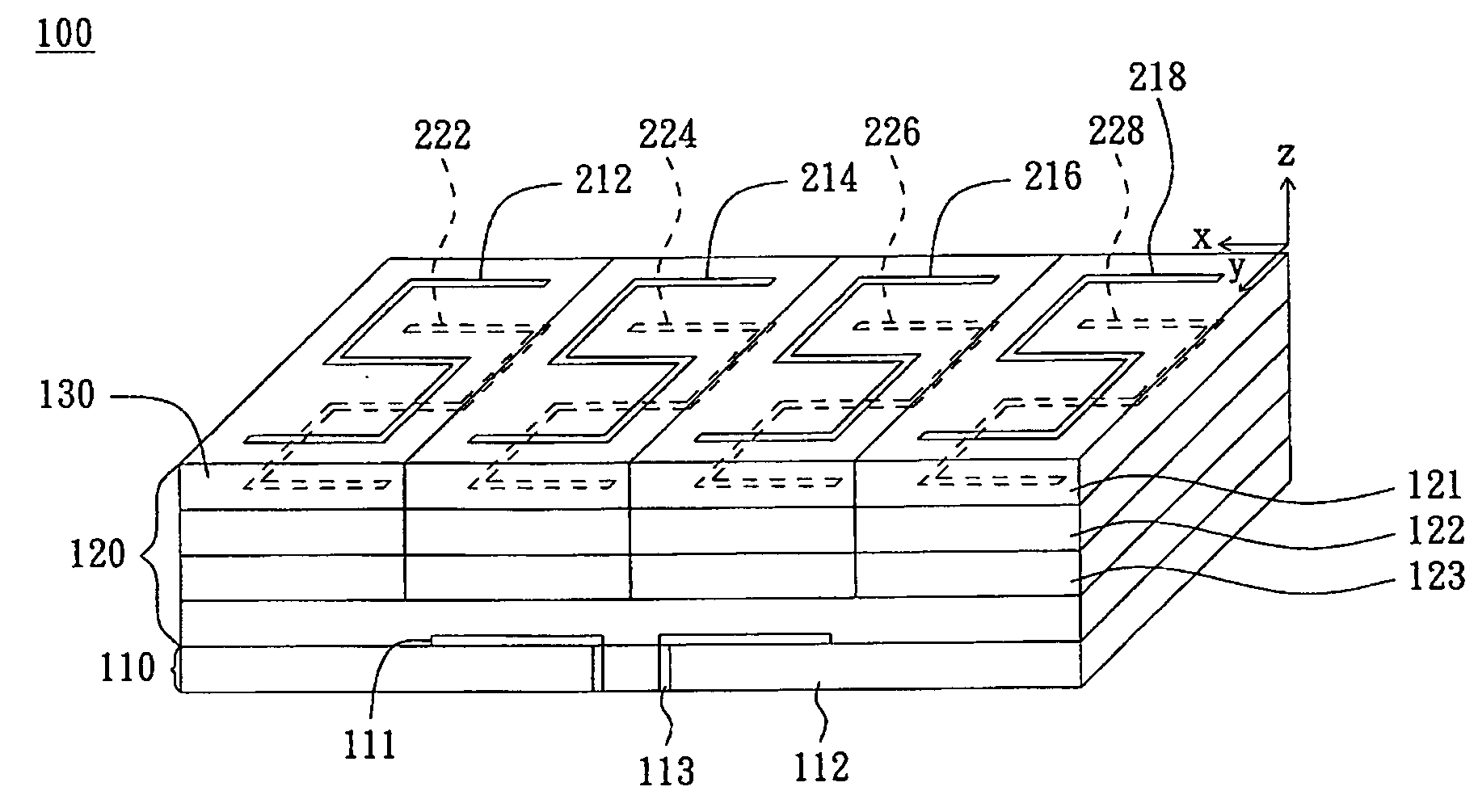
[0032]The invention provides an antenna structure with an antenna radome and a method of raising a gain thereof. A dielectric layer formed with metal patterns is utilized such that the antenna radome can be placed in a near-field zone of a radiating field of the antenna structure. Thus, the beamwidth of the radiating beams of the antenna structure can be converged to increase the gain of the antenna structure.

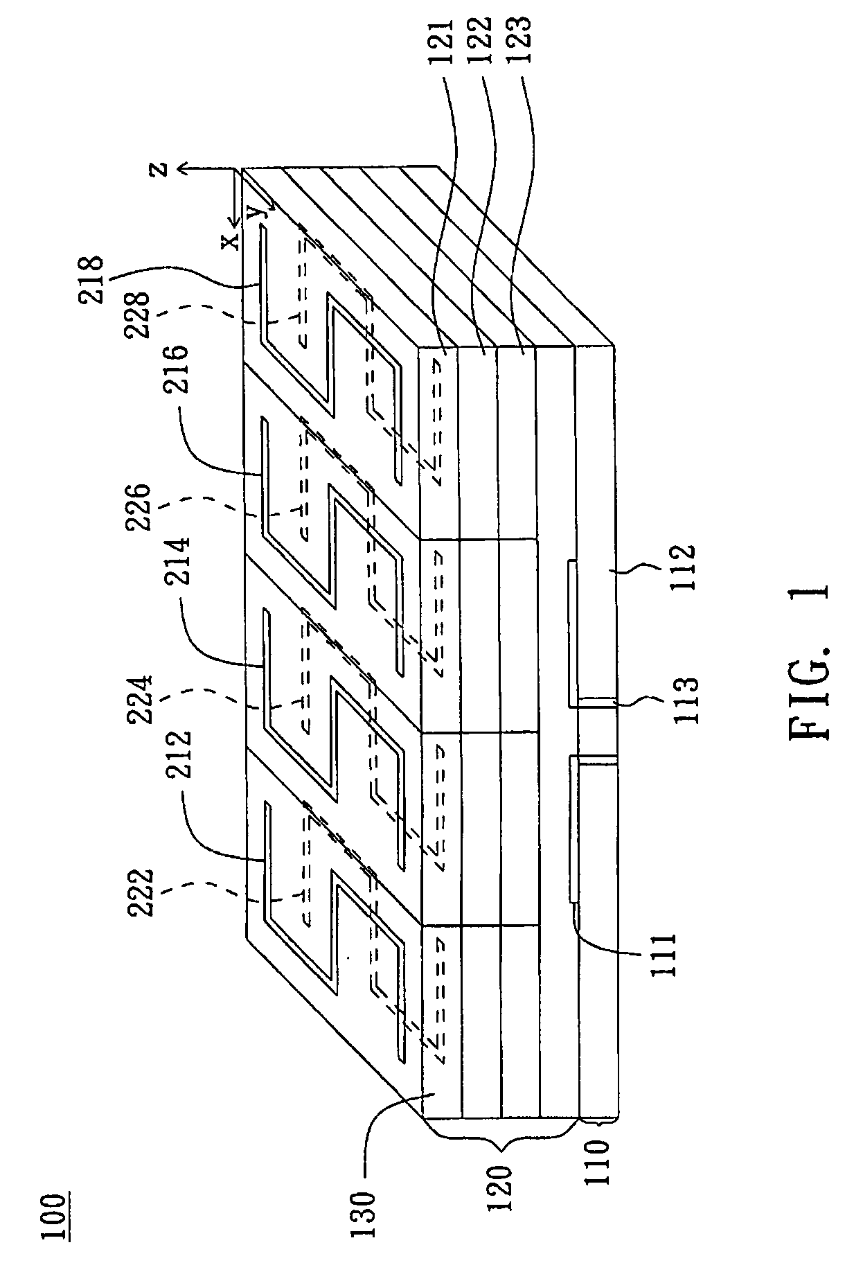
[0033]FIG. 1 is a schematic illustration showing an antenna structure 100 according to a preferred embodiment of the invention. Referring to FIG. 1, the antenna structure 100 includes a radiating element 110 and an antenna radome 120. The radiating element 110 includes a radiating main body 111, a medium element 112 and an antenna feeding end 113. The radiating main body 111 is disposed on the medium element 112, and the antenna feeding end 113 feeds signals. The radiating element 110 may be any type of antenna and is not restricted to a specific type of antenna.

[0034]The anten...


PUM


Abstract

An antenna structure includes a radiating element and an antenna radome. The antenna radome has at least one dielectric layer, which has an upper surface having many S-shaped metal patterns and a lower surface having many inverse S-shaped metal patterns corresponding to the S-shaped metal patterns. The S-shaped metal patterns are respectively coupled to the corresponding inverse S-shaped metal patterns to converge radiating beams outputted from the radiating element.

Description

CROSS-REFERENCE TO A RELATED APPLICATION[0001]This application is a Continuation-In-Part (CIP) of U.S. patent application Ser. No. 11 / 606,893 filed on Dec. 1, 2006.BACKGROUND OF THE INVENTION[0002]1. Field of the Invention[0003]The invention relates in general to an antenna structure with an antenna radome and a method for raising a gain thereof, and more particularly to an antenna structure, which has an antenna radome, a high gain and a simple structure, and a method for raising a gain thereof.[0004]2. Description of the Related Art[0005]Recently, the wireless communication technology is developed rapidly, so the wireless local area network (Wireless LAN) or the wireless personal area network (Wireless PAN) has been widely used in the office or home. However, the wired network, such as a DSL (Digital Subscriber Line), is still the mainstream for connecting various wireless networks. In order to wireless the networks in the cities and to build the backbone network appliance between...

Claims


Application Information

Patent Timeline
Patent Type & Authority Applications(United States)
IPC IPC(8): H01Q1/42H01Q1/38H01Q13/10
CPCH01Q1/38H01Q1/405H01Q15/0086H01Q15/0026H01Q9/0421
Inventor WU, CHUN YIHYEH, SHIH HUANGLIN, HUNG HSUAN
Owner IND TECH RES INST
Why Eureka
Try Eureka