Patch antenna and rectenna using the same

a technology of patch antenna and rectenna, which is applied in the field of patch antenna, can solve the problems of high production cost, large antenna size, and easy out of control of impedance matching, and achieve the effects of avoiding additional fabrication of another expensive patch, reducing production cost, and facilitating impedance matching

Active Publication Date: 2011-10-06
KOOKMIN UNIV IND ACAD COOP FOUND
View PDF5 Cites 26 Cited by
  • Summary
  • Abstract
  • Description
  • Claims
  • Application Information

AI Technical Summary

Benefits of technology

[0029]According to the antenna of the present invention, a capacitive coupling between the patch and the feeder line is obtained through the structure wherein the slot is formed on the ground plane and the feeder line is formed inside of the slot; when compared to the patch antennas of conventional technology, more easy impedance matching can be achieved by adjusting the design parameters of the slot and the feeder line on the ground plane; therefore, additional fabrication of another expensive patch can be avoided even in the worst-case.
[0030]According to the antenna of the present invention, it has the advantage that the production cost can be reduced by using a single patch instead of two patches; even though it has a dual-band frequency response, the size of the antenna may not be increased because another frequency response different than that of the patch is provided through adjustment of the design parameters of the T-shaped slot and the T-shaped feeder line.
[0031]According to the antenna of the present invention, it has the advantage that it can handle various signals since a circularly polarized wave and a linearly polarized wave can be transmitted and received in two different frequency bands.
[0032]According to the rectenna of the present invention, it has the advantage that it can supply more stable power compare to the conventional rectenna since it can generate an additional electrical energy by receiving non-relevant signals such as Wi-Fi or Bluetooth signal existing in free space mixed with the signals which are generally utilized for wireless power transmission.
[0033]According to the rectenna of the present invention, it has the advantage that it can be applied to various equipments because higher voltage than that of the input signal can be obtained through two-stage voltage multiplication in the rectifying unit.
[0034]According to the rectenna of the present invention, it has the advantage that the space required to install a rectenna can be reduced since the overall size can be reduced by forming the rectifying unit on the ground plane of the antenna.

Problems solved by technology

According to the first example of prior art, forming the minute gaps at both sides of the feeder line 121 is a very difficult process; furthermore, the impedance matching condition gets easily out of control due to a small variation in process parameters during actual fabrication of a patch antenna.
But, since this type of patch antenna utilizes two patches in transmitting and receiving signals having two different frequency bands, it requires high production cost and large antenna size to integrate two types of patch into a stacked form.

Method used


Image

  • Patch antenna and rectenna using the same
  • Patch antenna and rectenna using the same
  • Patch antenna and rectenna using the same

Examples


Embodiment Construction

[0045]Hereinafter, preferred exemplary embodiments of the present invention will be described in detail with reference to the attached drawings. Terminology and word used in the description and the claims of the present invention should not be construed as a typical or a lexical meaning, but construed as a meaning and concept in accordance with the technical spirit of the present invention on the basis of the principle that the inventors may properly define the concept of a terminology in order to best describe his / her invention.

[0046]Therefore, it should be understood that a variety of equivalents and modification examples that can replace the exemplary embodiments and configurations described in the drawings may exist at the time of this patent application since these exemplary embodiments and configurations are only a few examples of the present invention and not representing all the technical spirits of the present invention.

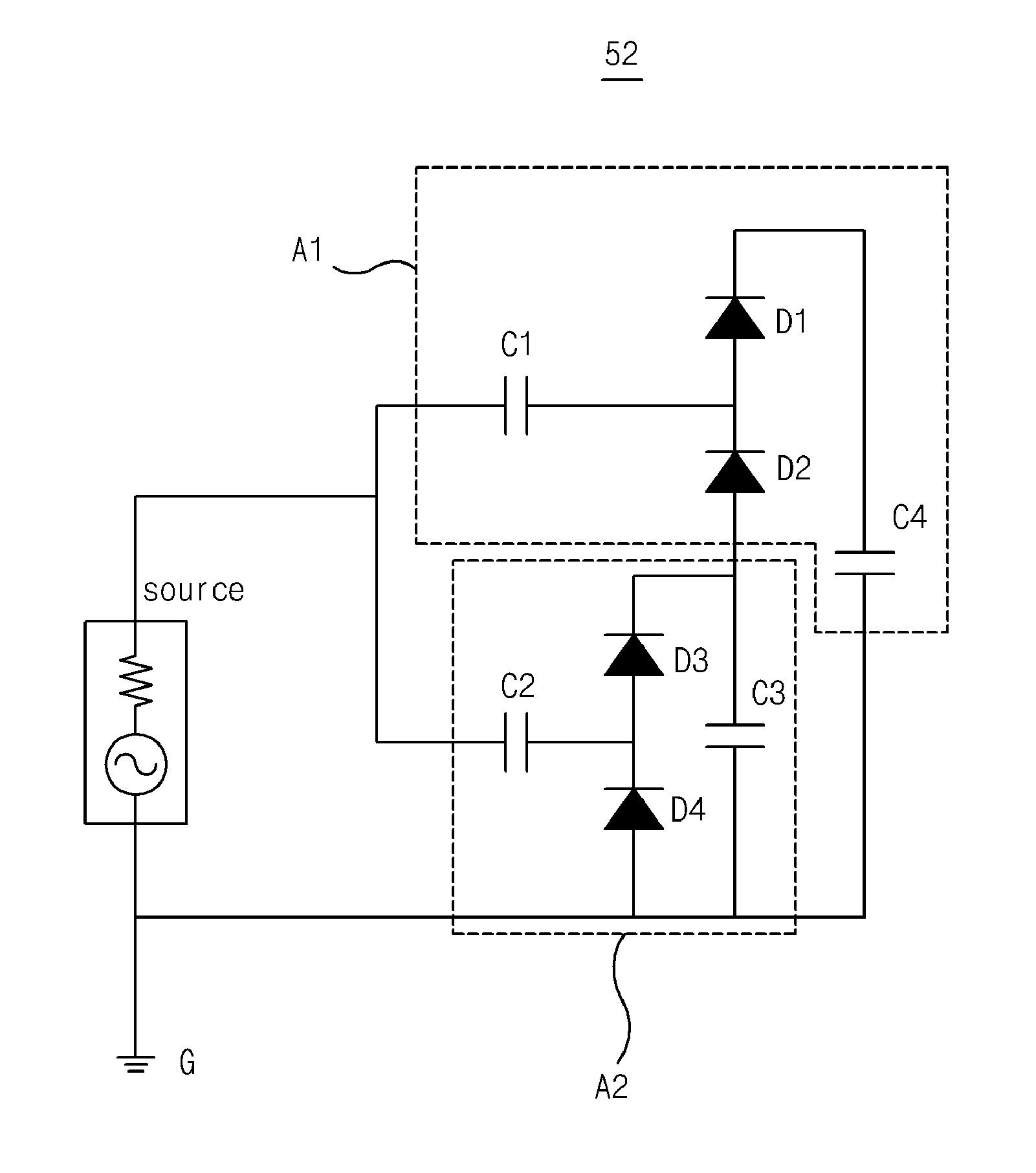
[0047]Hereinafter, a patch antenna and a rectenna in a...


PUM


Abstract

A patch antenna for receiving high frequency wireless signal and a rectenna using the same, more particularly, an impedance-matched patch antenna adopting a slot capacitive coupling structure and a rectenna capable of generating electrical energy from the wireless signals having different frequency band. A rectenna for receiving an A.C. wireless signal carrying electrical energy and converting the wireless signal into a D.C. electrical energy, is comprised of: a patch antenna for receiving the wireless signal comprising an dielectric substrate, a patch that is formed at the upper area of the surface of the dielectric substrate and providing the first frequency response characteristics, a ground plane formed on the other surface of the dielectric substrate, and an impedance matching means providing the second frequency response characteristics; and a rectifying unit that converts the wireless signal, received via the patch antenna, into a D.C. electrical energy by rectifying the wireless signal.

Description

BACKGROUND OF THE INVENTION[0001]1. Field of the Invention[0002]This invention relates to a patch antenna for receiving high frequency wireless signal and a rectenna using the same, more particularly, to an impedance-matched patch antenna adopting a slot capacitive coupling structure and a rectenna capable of generating electrical energy from the wireless signals having different frequency band.[0003]2. Description of the Related Art[0004]A patch antenna according to the first example of prior art is illustrated in FIG. 1. A patch antenna 10 illustrated in FIG. 1 adopts an in-set structure, wherein impedance matching is achieved by adjusting design parameters (a, b) of the gap 122 formed at each side of the feeder line 121 that is a partial extension from the bottom side of the patch 12 which is formed on a surface of the dielectric substrate 11.[0005]According to the first example of prior art, forming the minute gaps at both sides of the feeder line 121 is a very difficult process...

Claims


Application Information

Patent Timeline
Patent Type & Authority Applications(United States)
IPC IPC(8): H02M7/06H01Q1/50H01Q9/04
CPCH01Q1/248H01Q9/0428H01Q5/40H02J17/00H01Q9/0457H02J50/27H02J50/005
Inventor PARK, JUN-SEOKOH, HA-RYOUNGSEONG, YEONG-RAKROH, HYOUNG-HWANSEO, KI-WON
Owner KOOKMIN UNIV IND ACAD COOP FOUND
Why Eureka
Try Eureka