Boundary acoustic wave filter device

a filter device and acoustic wave technology, applied in the direction of impedence networks, electrical devices, etc., can solve the problems of insufficient attenuation in the stopband, deterioration of passband characteristics, and insufficient attenuation in the passband, so as to improve the attenuation, simplify the packaging structure of the boundary acoustic wave filter device, and improve the attenuation

Active Publication Date: 2008-05-29
MURATA MFG CO LTD
View PDF6 Cites 10 Cited by
  • Summary
  • Abstract
  • Description
  • Claims
  • Application Information

AI Technical Summary

Benefits of technology

[0026]In the boundary acoustic wave filter device according to a preferred embodiment of the present invention, the at least one longitudinally coupled resonator boundary acoustic wave filter, and the at least two one-terminal-pair boundary acoustic wave resonators are formed using the piezoelectric substrate and the dielectric film. Accordingly, the packaging structure of the boundary acoustic wave filter device can be more simplified and miniaturized than that of a surface acoustic wave filter device.
[0027]Furthermore, at least one boundary acoustic wave resonator of the at least two one-terminal-pair boundary acoustic wave resonators defines a serially connected boundary acoustic wave resonator. At least remaining one boundary acoustic wave resonator defines a parallel-connected boundary acoustic wave resonator. The anti-resonant frequency of the serially connected boundary acoustic wave resonator is located in a higher frequency range than a passband of the longitudinally coupled resonator boundary acoustic wave filter. Accordingly, the serially connected boundary acoustic wave resonator can improve the attenuation in a high frequency range located outside of the passband of the filter. Additionally, because the electromechanical coefficient of the boundary acoustic wave filter is large, impedance becomes inductive. This enables the impedance matching of the entire filter device in the passband to be easily achieved.
[0028]Since the resonant frequency of the parallel-connected boundary acoustic wave resonator is equal to or higher than the anti-resonant frequency of the serially connected boundary acoustic wave resonator, the attenuation in the high frequency range located outside of the passband can be more efficiently improved using the impedance change in the vicinity of the resonant frequency of the parallel-connected boundary acoustic wave resonator. Accordingly, the attenuation in the high frequency range located outside of the passband can be more increased.
[0029]When the piezoelectric substrate is a single-crystal-LiNbO3 substrate and when φ and θ of the Euler angles of the piezoelectric substrate are provided in a range of −31°≦φ≦31° and in a range of 90°≦θ≦130°, respectively, the electromechanical coefficient of the boundary acoustic wave filter can be more increased. This allows the impedance of the boundary acoustic wave filter to become more inductive, resulting in improving a state in which the impedance of the entire device in the passband is matched. Additionally, a power-flow angle can be reduced, and temperature characteristics can be improved.
[0030]When the IDTs are formed of one type of metal selected from a group of Al, Ti, Pt, Fe, Ni, Cr, Cu, Ag, W, Ta, and Au, or an alloy mainly including the metal, a boundary acoustic wave filter device with low loss can be provided.
[0031]When the dielectric film is formed of one type of material selected from a group of SiO2, SiN, crystal, LBO, langasite, langanite, and glass, the characteristic change due to the temperature of the boundary acoustic wave filter device can be reduced.

Problems solved by technology

For this reason, when impedance in the stopband is set to be low in order to sufficiently increase attenuation in the vicinity of the passband, there is a disadvantage in that impedance in the passband does not become sufficiently high.
In such a case, some of the signals in the passband flow to the capacitor 513, resulting in a deterioration in the characteristics of the passband.
Conversely, when the impedance to the signals in the passband is set to be sufficiently high, there is a disadvantage in that the impedance in the stopband does not become sufficiently low, resulting in the attenuation in the stopband not being sufficiently increased.
Thus, because all of the filter, the serially connected surface acoustic wave resonator, and the parallel-connected surface acoustic wave resonator seem to be capacitive, there is a disadvantage in that it is difficult to achieve impedance matching in the passband.
Accordingly, there has been a disadvantage in that it is difficult to achieve impedance matching in the passband.
Thus, in the surface acoustic wave filter device in the related art, the parallel-connected surface acoustic wave resonator, which is connected in parallel to the surface acoustic wave filter, has not been used to improve the attenuation in the high frequency range located outside of the passband.

Method used


Image

  • Boundary acoustic wave filter device
  • Boundary acoustic wave filter device
  • Boundary acoustic wave filter device

Examples


Embodiment Construction

[0038]Preferred embodiments of the present invention will be described below with reference to the accompanying drawings.

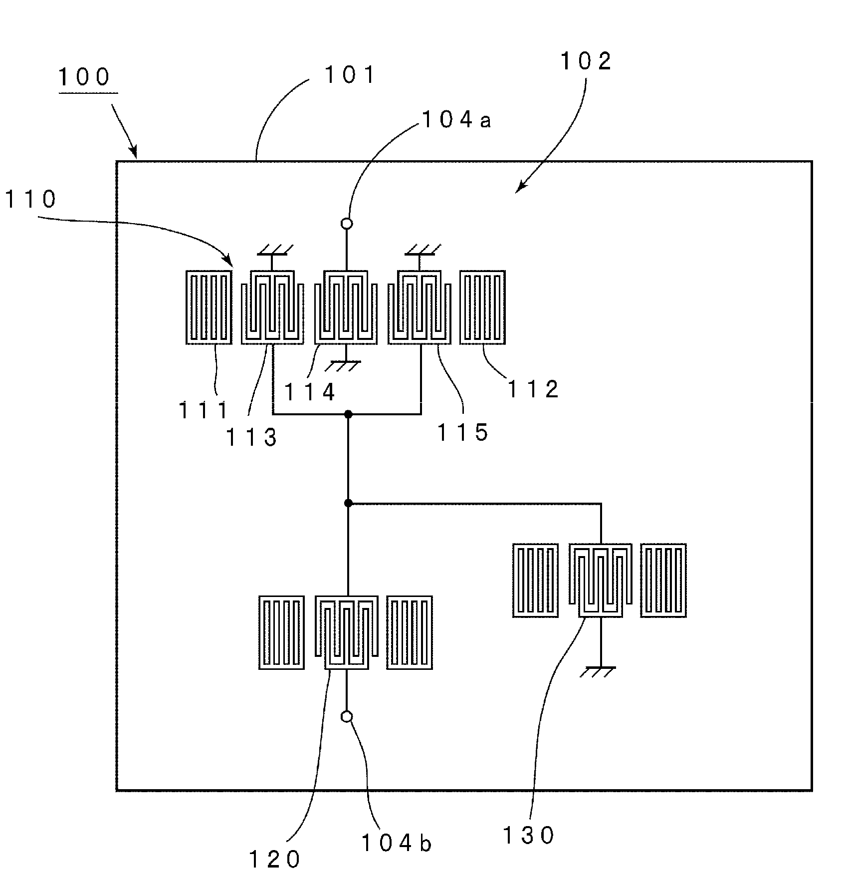
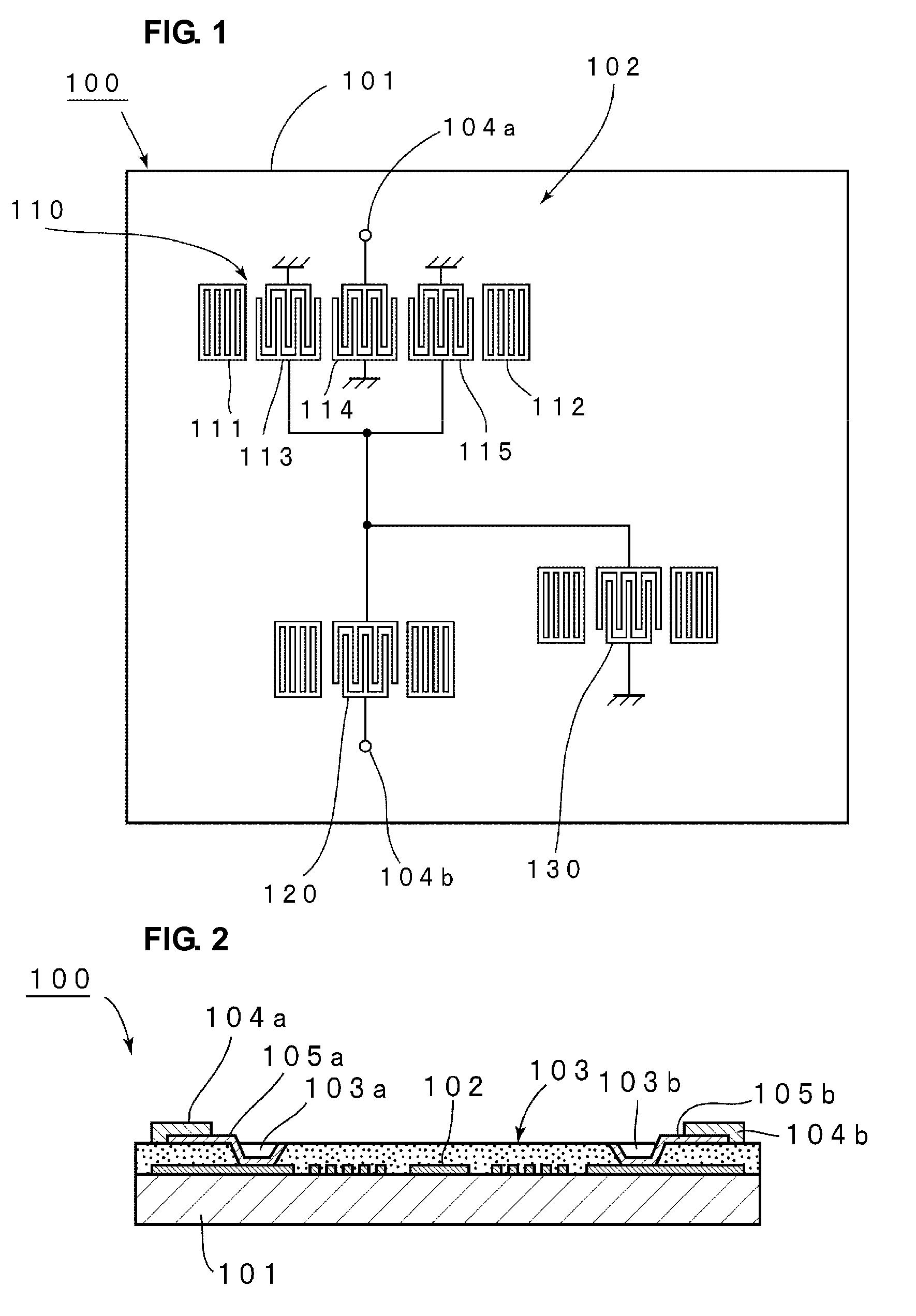
[0039]FIG. 1 is a schematic plan view of the electrode configuration of a boundary acoustic wave filter device according to a preferred embodiment of the present invention, and FIG. 2 is a schematic front-sectional view describing a substantial portion of the boundary acoustic wave filter device.

[0040]As shown in FIG. 2, the boundary acoustic wave filter device 100 according to the present preferred embodiment preferably includes a LiNbO3 substrate 101 formed of a single crystal of LiNbO3 as a piezoelectric substrate. A SiO2 film 103 overlies the LiNbO3 substrate 101 as a dielectric film. The boundary acoustic wave filter device 100 according to the present preferred embodiment utilizes an SH-type boundary acoustic wave propagating along a boundary surface between the LiNbO3 substrate 101 and the SiO2 film 103.

[0041]In FIG. 2, an electrode pattern 102 for passive ...


PUM


Abstract

A boundary acoustic wave filter device capable of increasing an out-of-band attenuation includes a dielectric film formed on a piezoelectric substrate, at least one longitudinally coupled resonator boundary acoustic wave filter having a plurality of IDTs disposed along a boundary between the piezoelectric substrate and the dielectric film, and at least two one-terminal-pair boundary acoustic wave resonators. At least one boundary acoustic wave resonator is connected in series to the longitudinally coupled resonator boundary acoustic wave filter, and at least remaining one boundary acoustic wave resonator is connected in parallel to the longitudinally coupled resonator boundary acoustic wave filter. An anti-resonant frequency of the serially connected boundary acoustic wave resonator is located in a higher frequency range than a passband of the boundary acoustic wave filter device, and a resonant frequency of the parallel-connected boundary acoustic wave resonator is equal to or higher than the anti-resonant frequency of the serially connected boundary acoustic wave resonator.

Description

BACKGROUND OF THE INVENTION[0001]1. Field of the Invention[0002]The present invention relates to a boundary acoustic wave filter device utilizing a boundary acoustic wave propagating along a boundary surface between a piezoelectric substrate and a dielectric film, and more particularly, the present invention relates to a boundary acoustic wave filter device having a circuit configuration in which a one-terminal-pair boundary acoustic wave resonator is connected to a longitudinally coupled resonator boundary acoustic wave filter.[0003]2. Description of the Related Art[0004]Recently, surface acoustic wave filter devices have been used as bandpass filters in RF stages of mobile phones because of their smaller size and excellent filter characteristics.[0005]For example, in Japanese Unexamined Patent Application Publication No. 2002-64358, a compound surface acoustic wave filter device in which a one-port-type surface acoustic wave resonator is connected in series to a longitudinally cou...

Claims


Application Information

Patent Timeline
Patent Type & Authority Applications(United States)
IPC IPC(8): H03H9/00
CPCH03H9/02559H03H9/0222H03H9/145H03H9/25
Inventor KANDO, HAJIMENAKAHASHI, NORIHIKOSHIBAHARA, TERUHISA
Owner MURATA MFG CO LTD
Why Eureka
Try Eureka