Impact resistant, thin ply composite structures and method of manufacturing same

a composite structure and thin ply technology, applied in the field of impact resistance, thin ply composite structure and method of manufacturing same, can solve the problems of brittle nature of rcc, limited performance and range of applications of these materials, and difficulty in using carbon nanotubes (cnts) alone as reinforcement to enhance the mechanical properties of a material, and achieve the effect of greater impact resistan

Inactive Publication Date: 2008-08-05
KAZAK COMPOSITES
View PDF4 Cites 36 Cited by
  • Summary
  • Abstract
  • Description
  • Claims
  • Application Information

AI Technical Summary

Benefits of technology

[0009]The present thin ply composite material allows the manufacture of thinner-walled components with impact and other mechanical properties equivalent to thicker parts made by conventional technology, resulting in more lightweight structures.

Problems solved by technology

The performance and range of applications of these materials are limited, however, by their relatively high susceptibility to impact damage.
For example, the space shuttle Columbia accident is believed to have been caused by impact damage to the reinforced carbon-carbon (RCC) leading edge thermal protection system.
The brittle nature of the RCC may be due to the conventional 2D or 2.5D carbon fiber ply architecture.
Using carbon nanotubes (CNTS) alone as reinforcement to enhance the mechanical properties of a material is challenging.
In particular, dispersing CNTs to obtain uniform distributions in a composite is difficult.
The use of CNTs is also costly, particularly at such large volumes.

Method used


Image

  • Impact resistant, thin ply composite structures and method of manufacturing same
  • Impact resistant, thin ply composite structures and method of manufacturing same
  • Impact resistant, thin ply composite structures and method of manufacturing same

Examples


Embodiment Construction

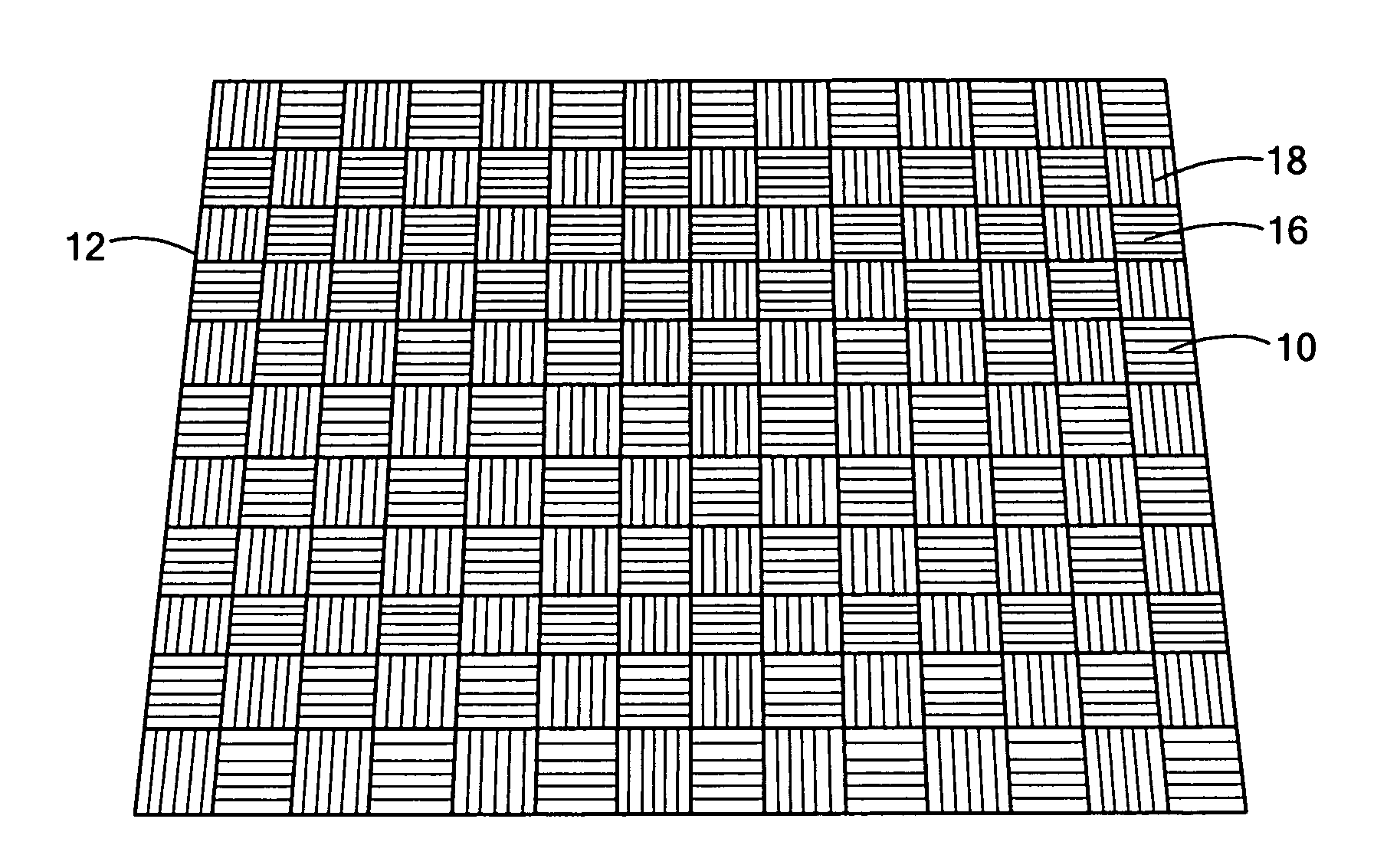
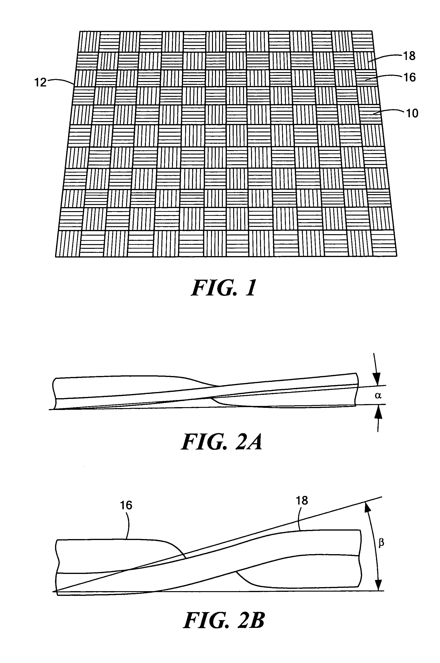
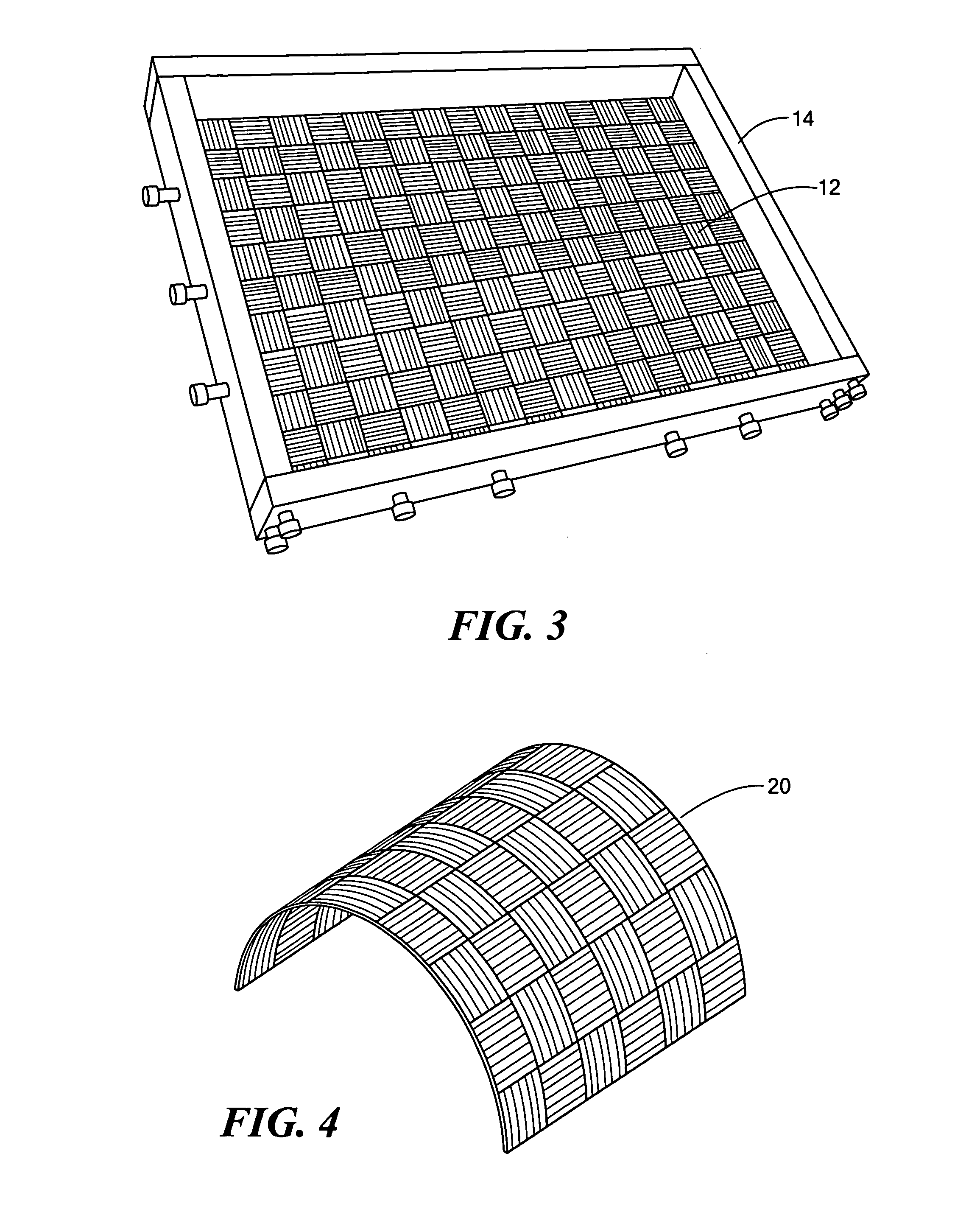
[0018]In the present invention, a reinforced carbon-carbon (RCC) composite material is provided having improved impact resistance. The composite material is formed from a fiber reinforcement of layers or plies of thin ply carbon fiber fabric impregnated with a carbon matrix and preferably further reinforced with carbon nanotubes. The fabrication of the RCC composite begins with a preform 12 of dry or preimpregnated thin ply carbon fiber fabric layers. See FIG. 1. The preform is infiltrated with a carbon precursor matrix material and cured to form a precursor composite material. Various processes, such as vacuum assisted resin transfer matrix molding (VARTM), hot press molding, and pultrusion, can be used to form and cure the precursor composite material. Thereafter, the precursor composite material undergoes a carbonization process to convert the precursor matrix material to carbon through thermal degradation and a densification process to achieve a desired bulk density.

[0019]The th...


PUM

PropertyMeasurementUnit
thicknessaaaaaaaaaa
widthaaaaaaaaaa
thicknessaaaaaaaaaa

Abstract

A reinforced carbon-carbon (RCC) composite material has improved impact resistance. The RCC composite material is formed from a fiber reinforcement of layers or plies of thin ply carbon fiber fabric impregnated with a carbon matrix. Carbon nanotube reinforcement in the matrix further improves impact resistance. The stacking arrangement of the plies of the thin ply fabric also further improves impact resistance.

Description

CROSS REFERENCE TO RELATED APPLICATIONS[0001]This application claims the benefit under 35 U.S.C. § 119(e) of U.S. Provisional Application No. 60 / 643,243, filed on Jan. 12, 2005, and U.S. Provisional Application No. 60 / 645,797, filed on Jan. 21, 2005, the disclosures of which are incorporated by reference herein.STATEMENT REGARDING FEDERALLY SPONSORED RESEARCH OR DEVELOPMENT[0002]This invention was made under Air Force SBIR Contract # FA8650-05-M-5030. The government may have certain rights in this invention.BACKGROUND OF THE INVENTION[0003]Carbon-carbon (C / C) composite materials offer excellent combinations of specific thermal conductivity and specific stiffness. Also, C / C offers low density, high stiffness, low coefficient of thermal expansion, zero outgassing in the space environment, and a unique high temperature capability. C / C composites graphitized to temperatures greater than 2200° C. provide high through-the-thickness (kz) conduction of 25 to 100 W / m-K (compared to kz=1-5 W / ...

Claims


Application Information

Patent Timeline
Patent Type & Authority Patents(United States)
IPC IPC(8): D03D15/00B32B17/12B32B18/00B32B5/26B32B7/12
CPCB82Y30/00C04B35/83D03D15/00D03D15/0088C04B2235/5256C04B2235/5268D10B2401/063D10B2101/12C04B2235/5288Y10T442/3041Y10T442/3488Y10T428/31511Y10T428/31504Y10T428/249927Y10T442/3683Y10T428/249945Y10T442/3496Y10T442/335Y10T428/31594D03D15/46B32B18/00C04B2237/385D03D15/275
Inventor BYSTRICKY, PAVELFANUCCI, JEROME P.
Owner KAZAK COMPOSITES
Why Eureka
Try Eureka