Antenna and radio device comprising same

A technology for wireless devices and antennas, applied to devices that enable antennas to work in different bands at the same time, antenna support/installation devices, antennas, etc., can solve problems such as inappropriate use of built-in antennas and increased cost of portable phones

Inactive Publication Date: 2003-09-10
PANASONIC CORP
View PDF0 Cites 9 Cited by
  • Summary
  • Abstract
  • Description
  • Claims
  • Application Information

AI Technical Summary

Problems solved by technology

[0007] However, the operating frequency band of the above-mentioned existing antenna as one of the important electrical characteristics is only about 30% of the specific bandwidth at the most. In order to improve this performance, the shape of the antenna has to be enlarged. In order to adapt to the market It is not suitable for use with built-in antennas that require such a small broadband and high sensitivity
In addition, even if broadband and high sensitivity are achieved by sacrificing size and thickness, it is necessary to provide a complicated impedance matching circuit between the antenna and the high-frequency circuit section, which causes a problem of increased cost of the mobile phone

Method used


Image

  • Antenna and radio device comprising same
  • Antenna and radio device comprising same
  • Antenna and radio device comprising same

Examples


Embodiment 2

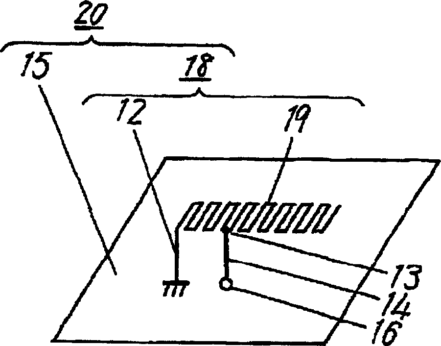
[0061] Fig. 2 shows the configuration diagram of the antenna in Embodiment 2 of the present invention. In Fig. 2, the main part 18 of the antenna is constituted by a repeatedly bent antenna element (hereinafter referred to as a repeatedly bent antenna or a repeatedly bent element portion). ) except that the antenna 19 is configured, the antenna 20 is configured in the same manner as in the first embodiment described above.

[0062] According to this configuration, desired impedance characteristics can be easily obtained in a desired frequency band by adjusting the distance between the short wire 12 and the feed point 13 and the line width, length, and pitch of the repeatedly meandering element 19 . Therefore, the miniaturization of the antenna can be realized while achieving wide bandwidth and high sensitivity. In addition, since the helical antenna element in Embodiment 1 is used instead of the helical antenna element, it is possible to further reduce the thickness.

Embodiment 3

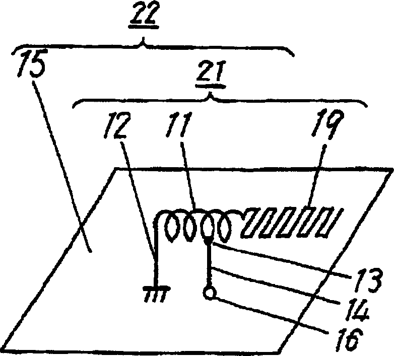
[0064] Fig. 3 shows the structure of the antenna in Embodiment 3 of the present invention. In Fig. 3, the main part of the antenna 21 is the same as that of the above-mentioned embodiment and Antenna 22 having the same configuration as in Embodiment 2.

[0065] According to this configuration, by adjusting the distance between the short wire 12 and the feeding point 13 and the line width and length pitch of the helical element part and the repeatedly meandering element part 19, it is possible to easily perform the process for obtaining a desired impedance within a desired frequency band. characteristic. Therefore, it is possible to realize wide-band and high-sensitivity antennas with higher precision. In this third embodiment, since the antenna element 21 is formed by combining the helical element portion 11 and the repeatedly bent element portion 19, a more flexible miniaturization and thinner design of the antenna can be realized.

[0066] In addition, in this embodiment, ...

Embodiment 4

[0068] Fig. 4 shows the antenna constitution in the embodiment 4 of the present invention, and in Fig. 4, the main part 24 of the antenna except that the short wire 12 of the antenna element and the feeding point 13 is made into a linear conductor, constitutes the same antenna as the above-mentioned embodiment. 25.

[0069] According to this configuration, it is possible to increase the degree of freedom in design, in addition to realizing broadband widening, high sensitivity, and miniaturization of the antenna.


PUM


Abstract

An inverted F antenna and a radio device comprising the same. The antenna element comprises a grounding conductor plate and a conductor spaced from the grounding conductor plate, disposed above the grounding conductor plate, and made of a conductor at least part of which is generally spiral. A stab connects one end of the antenna element and the grounding conductor plate. A feeder connects a feeding point on the antenna element at a predetermined distance from the one end to an external circuit. The antenna element is secured to the grounding conductor plate through a holding member of a dielectric material.

Description

technical field [0001] The present invention relates to an antenna mounted on a wireless device using mobile communication and the like and a wireless device using the antenna. Background technique [0002] In recent years, as the demand for wireless devices for mobile communication has increased, it is desired to diversify the communication methods and release high-performance, compact and light-weight wireless devices that can handle various communications with one wireless device. Therefore, development of antennas to be mounted on these wireless devices is inevitably desired. [0003] A typical example of such mobile communication is a mobile phone system, which is widely used in various regions of the world, and the use frequency bands also vary depending on the region. For example, the frequency band used by a digital portable telephone system is 810-960MHz in Personal Digital Cellular 800 (PDC800) in Japan, 890-960MHz in Group Special Mobile Community (GCM) in Europe...

Claims


Application Information

Patent Timeline
Patent Type & Authority Applications(China)
IPC IPC(8): H01Q3/24H01Q1/24H01Q1/36H01Q5/10H01Q9/04H01Q9/30H01Q9/36H01Q9/42H01Q21/30
CPCH01Q1/243H01Q1/36H01Q9/42H01Q1/242H01Q9/0407H01Q13/08
Inventor 大原正广高木直志稻继进
Owner PANASONIC CORP
Why Eureka
Try Eureka