A low-altitude antenna device

An antenna device and a low-height technology, applied in the field of low-height antenna devices, can solve the problem of insufficient multi-resonance effect, and achieve the effect of suppressing height and realizing broadband.

Inactive Publication Date: 2013-04-03
HARADA IND CO LTD
View PDF6 Cites 1 Cited by
  • Summary
  • Abstract
  • Description
  • Claims
  • Application Information

AI Technical Summary

Problems solved by technology

Therefore, sometimes the multi-resonance effect cannot be fully obtained

Method used


Image

  • A low-altitude antenna device
  • A low-altitude antenna device
  • A low-altitude antenna device

Examples


Embodiment Construction

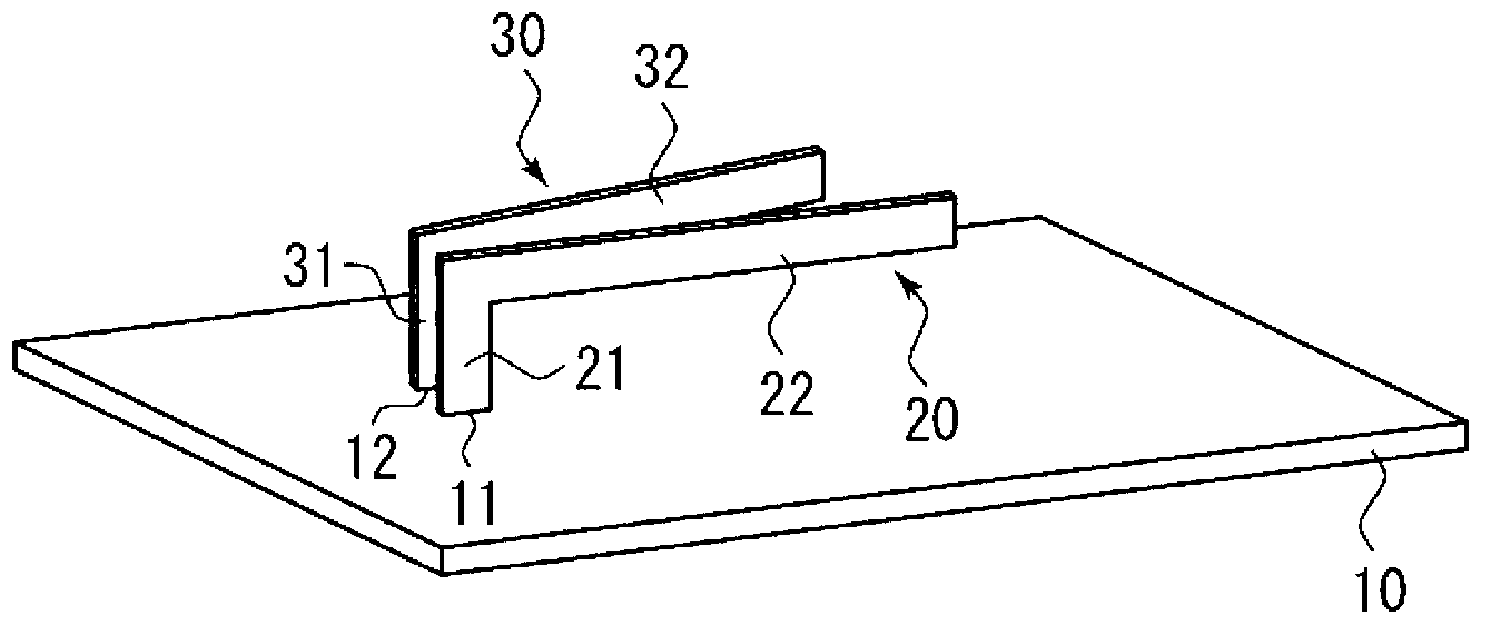
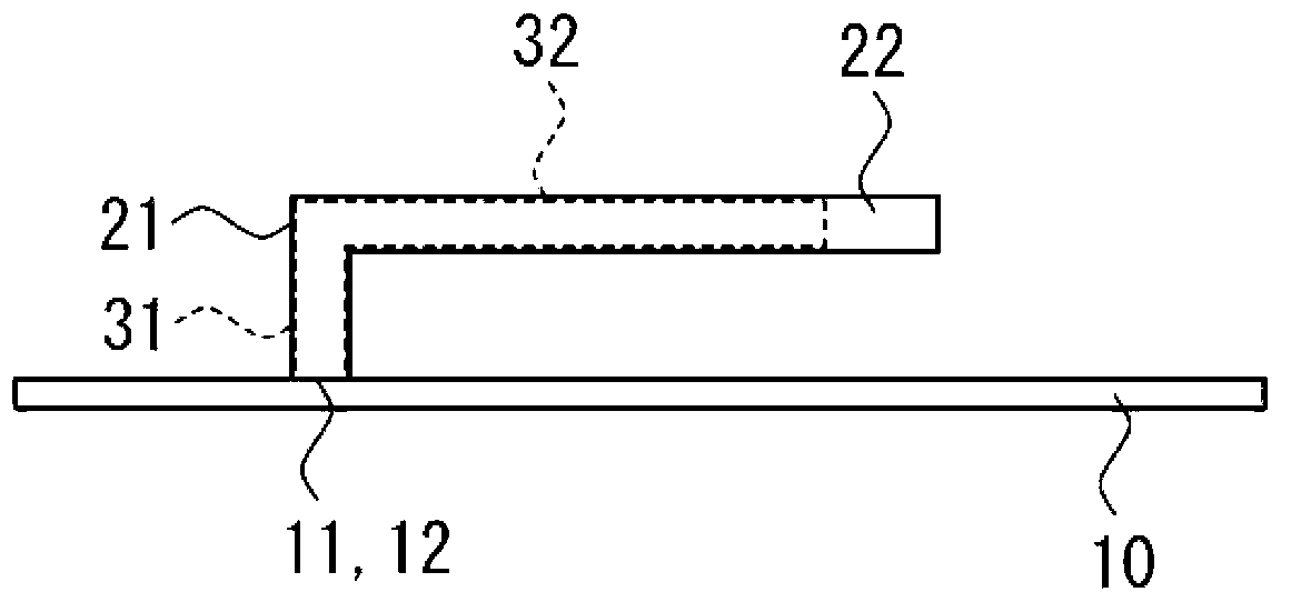
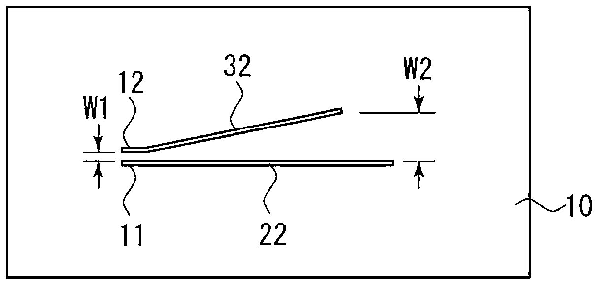
[0035] Hereinafter, modes for implementing the present invention will be described with reference to examples shown in the drawings. see Figure 1a to Figure 1c , Figure 1a is shown as a perspective view of the low-height antenna arrangement of the present invention; Figure 1b is shown as a side view of the low height antenna arrangement of the present invention; Figure 1c Shown is a top view of the low height antenna arrangement of the present invention. As shown in the figure, the low-height antenna device of the present invention mainly includes a conductor plate 10 , an antenna element 20 and a parasitic element 30 .

[0036] The conductor plate 10 is a conductive plate-shaped body having a feed point 11 and a short-circuit point 12 . To the feeding point 11, for example, a signal line of a coaxial cable for feeding from a tuner is connected. In addition, the short-circuit point 12 is a ground, for example, a direct short-circuit with the conductor plate 10 . The c...


PUM


Abstract

The invention provides a low-altitude antenna device capable of fully achieving broadband while inhibiting altitude. The low-altitude antenna device comprises a conductor plate (10), a reverse-L-shaped or reverse-F-shaped antenna element (20), and a passive element (30). The antenna element (20) comprises an antenna protruding portion (21) protruding from the conductor plate (10), and an antenna main body portion (22) deviously extended from the front of the antenna protruding portion (31). The passive element (30) comprises a passive protruding portion (31) protruding from the conductor plate (10), and a passive main body portion (32) deviously extended from the front of the passive protruding portion (31). In order to be stimulated from the antenna protruding portion (21), at least part of the passive protruding portion (31) is extended from the antenna protruding portion (21) in a manner opposite surface and in parallel. Observed from the top of the conductor plate (10), the passive main body portion (32) is extended in a manner that the distance between the passive main body portion (32) and the antenna main body portion (22) is more than that between the passive protruding portion (31) and the antenna protruding portion (21).

Description

technical field [0001] The present invention relates to a low-height antenna device, in particular to a low-height antenna device that uses passive elements to realize wideband through multi-resonance effects. Background technique [0002] Currently, various antenna devices are mounted on vehicles, and examples of such antenna devices include AM / FM radio antennas capable of receiving AM broadcasts and FM broadcasts. As an antenna for AM / FM radio, a rod antenna is generally used. The rod antenna is formed of an element (helical element) part covered by a radome and made of a helical-shaped conductor and a base part for mounting the element part. [0003] When the rod antenna is attached to the vehicle body, the component part protrudes greatly from the vehicle body, which may damage the appearance or design of the vehicle, and may be damaged when entering the garage or washing the car. In addition, the component part may be installed exposed to the outside of the vehicle. b...

Claims


Application Information

Patent Timeline
IPC IPC(8): H01Q1/36H01Q1/08H01Q1/12
Inventor 佐藤真人岩崎浩幸田代有吾
Owner HARADA IND CO LTD
Why Eureka
Try Eureka