Workpiece transfer apparatus

a technology of workpieces and transfer apparatuses, which is applied in the direction of load-engaging elements, program-controlled manipulators, gripping heads, etc., can solve the problems of difficult to achieve the transfer of relatively large workpieces w at high speed, the height of the hand is not desirable, and the transfer speed is limited. achieve the effect of high speed and without increasing the height of the apparatus

Active Publication Date: 2012-08-09
DAIHEN CORP
View PDF8 Cites 12 Cited by
  • Summary
  • Abstract
  • Description
  • Claims
  • Application Information

AI Technical Summary

Benefits of technology

[0012]The present invention has been proposed under the circumstances described above. It is therefore an object of the present invention to provide a workpiece transfer apparatus suitable for transferring workpieces at high speed, without increasing the height of the apparatus.
[0022]In the workpiece transfer apparatus according to the present invention, the motor for driving the hand and part of the transmission mechanism are arranged in the internal space of the first arm. With this arrangement, the height of the transmission mechanism within the distal end of the second arm is suppressed, and the total height of the stationary base and the elevation base is also suppressed. Further, since the transmission mechanism is arranged to extend in a region from an interior of the first arm through an interior of the second arm, the power transmission path from the motor to the hand is relatively short. This structure is suitable for workpiece transfer at high speed and with high accuracy. Moreover, since the speed reducer, which is one of the elements constituting the transmission mechanism, is arranged in the first arm, the rotation element operates stably. Thus, the workpiece transfer apparatus according to the present invention is capable of transferring even a relatively large workpiece at high speed and with high accuracy.

Problems solved by technology

This provides limitation on the increase in the workpiece transfer speed.
Such an increase in height of the hand 945 is not desirable, because the lowest position where workpieces can be transferred in the load ports 91 cannot be changed in most cases due to various limitations.
Thus, with the above-described conventional structure, it is difficult to achieve transfer of relatively large workpieces W at high speed by increasing the size of the motor 947 or the speed reducer 949.
With the above-described conventional structure, however, the provision of two motors and two transmission mechanisms increases the height of the workpiece transfer apparatus 94 and hence increase the height of the hand 945, so that it is difficult to adapt such an apparatus for relatively large workpieces W.

Method used


Image

  • Workpiece transfer apparatus
  • Workpiece transfer apparatus
  • Workpiece transfer apparatus

Examples


Embodiment Construction

[0032]Preferred embodiments of the present invention are described below with reference to the accompanying drawings.

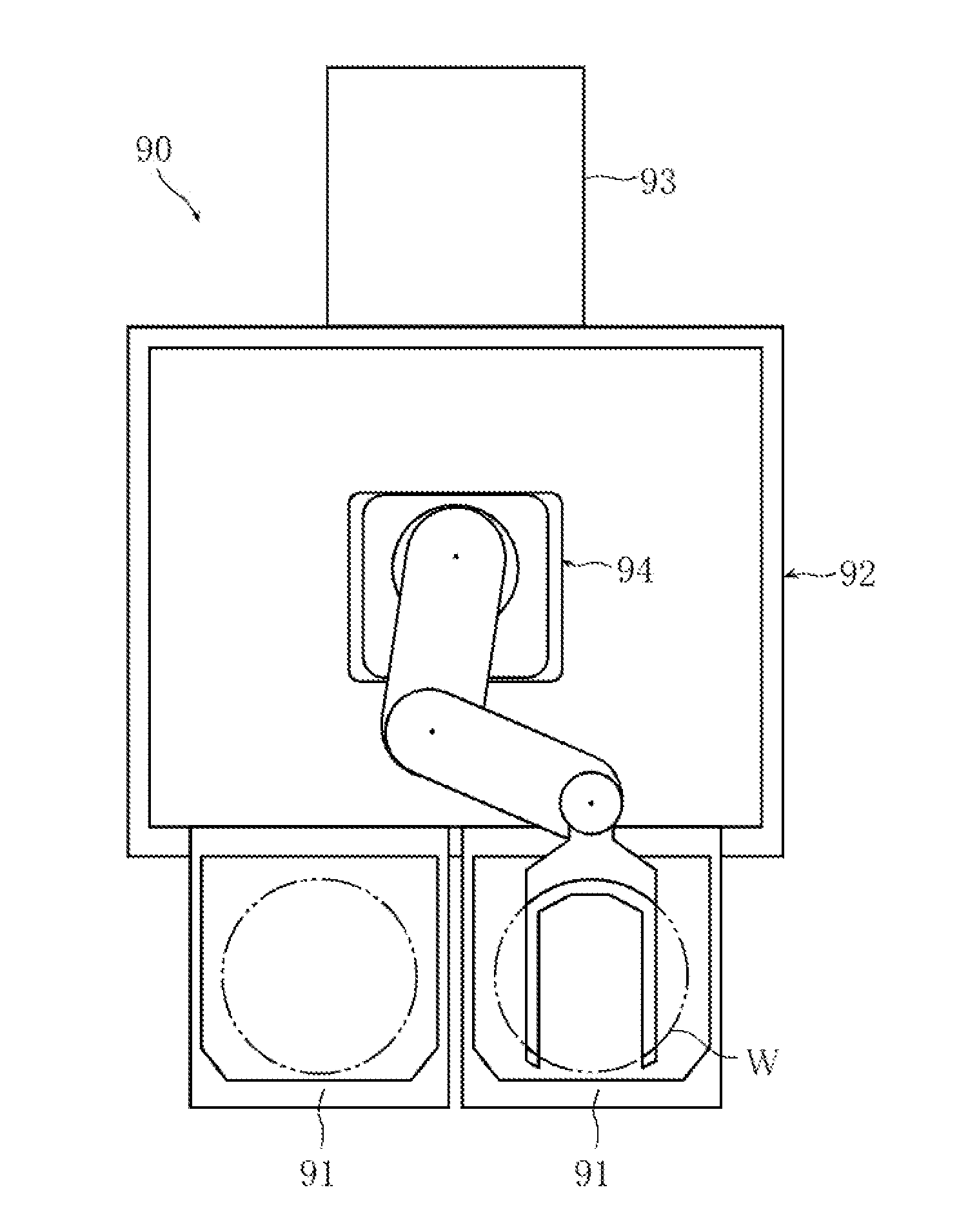
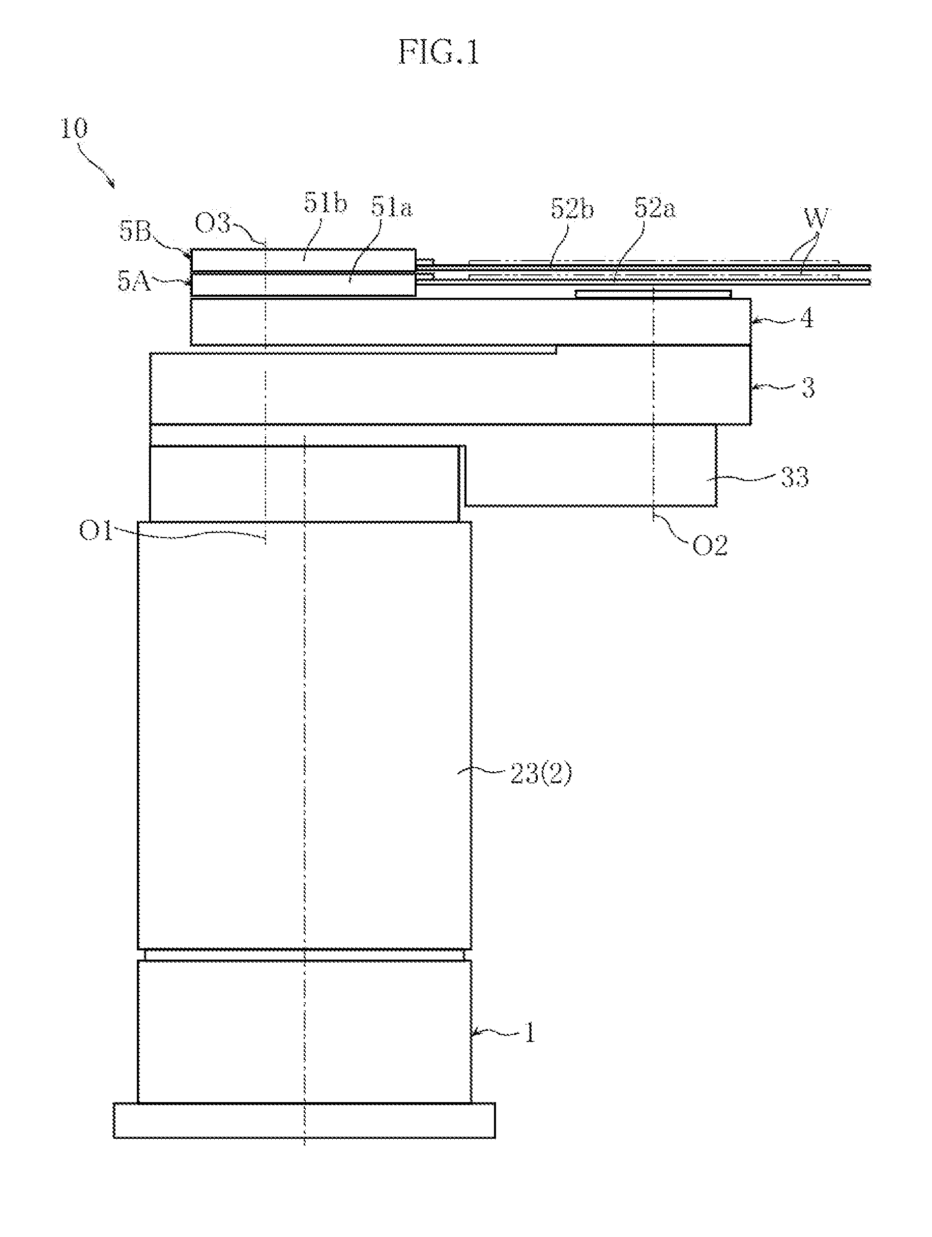
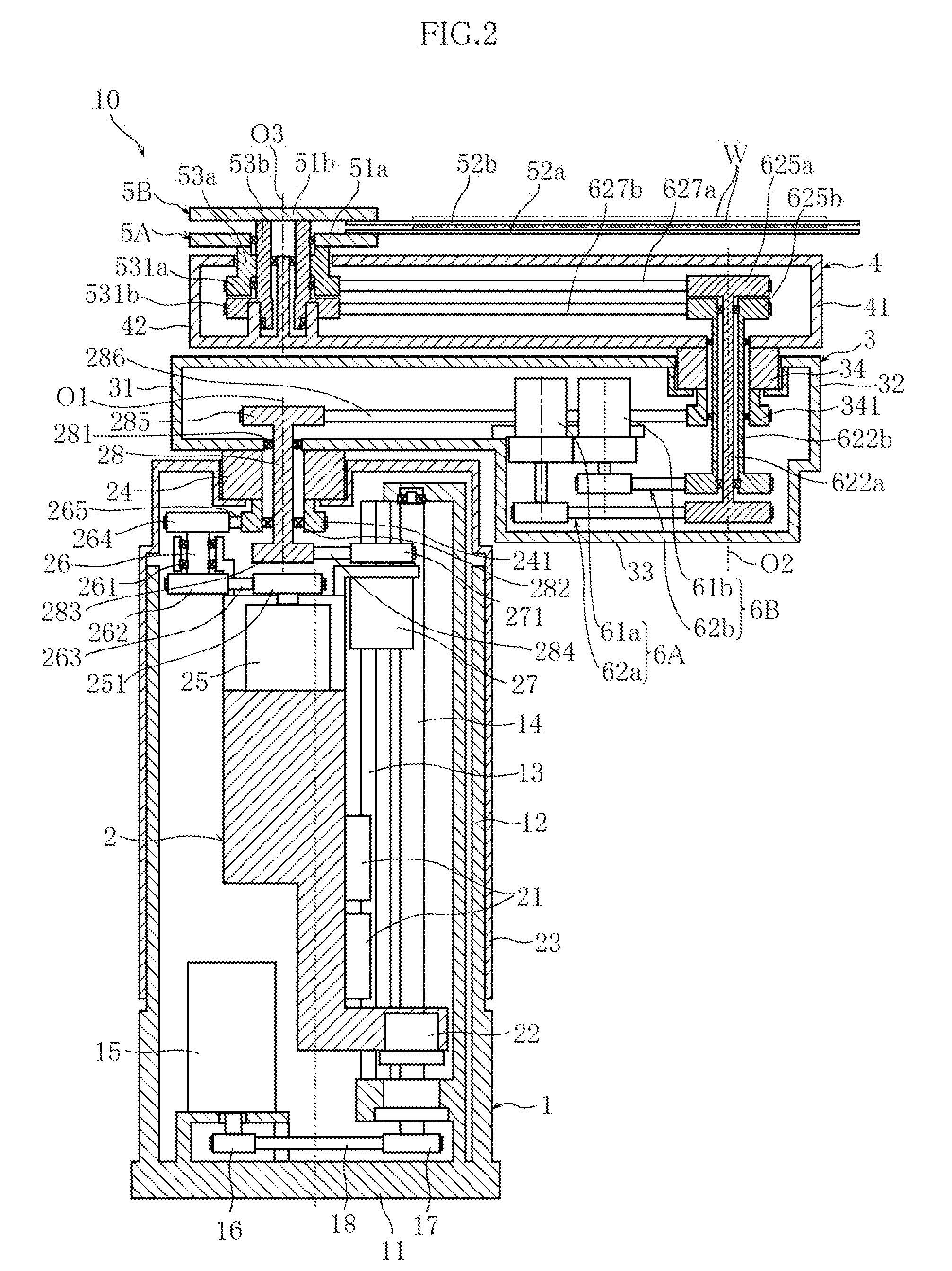
[0033]FIGS. 1-6 show a workpiece transfer apparatus according to an embodiment of the present invention. The workpiece transfer apparatus 10 of this embodiment is designed to transfer workpieces W in the form of a thin plate such as a wafer, and includes a stationary base 1, an elevation base 2, elongated lower arm 3 and upper arm 4, two hands 5A and 5B for holding a workpiece W, and a hand driving mechanisms 6A, 6B for driving the hands for rotation.

[0034]As shown in FIG. 2, the stationary base 1 is structured as a hollow housing which is substantially rectangular in cross section and includes a bottom 11 and a side wall 12.

[0035]The elevation base 2 is supported by the stationary base 1 movably in the vertical direction. A pair of vertically extending guide rails 13 are provided in the stationary base 1. The elevation base 2 is provided with a slider 21. The slider ...


PUM


Abstract

A workpiece transfer apparatus includes a stationary base, an elevation base, first and second arms, a workpiece-holding hand, and a driving mechanism for the hand. The first arm is supported on the elevation base so as to be rotatable about a first vertical axis. The second arm is supported on the distal end of the first arm such that the second arm is rotatable about a second vertical axis. The hand is supported on the distal end of the second arm so as to be rotatable about a third vertical axis. A motor is arranged in the first arm, whereas a transmission is arranged to extend in a region from the interior of the first arm through the interior of the second arm.

Description

BACKGROUND OF THE INVENTION[0001]1. Field of the Invention[0002]The present invention relates to a workpiece transfer apparatus for transferring workpieces in the form of a thin plate. Specifically, the invention relates to a workpiece transfer apparatus for transferring e.g. wafers in the process of manufacturing semiconductor devices.[0003]2. Description of the Related Art[0004]In the manufacture of semiconductor devices, a robot for transferring workpieces such as wafers is used (see JP-A-2003-188231, for example). Such a workpiece transfer apparatus transfers workpieces between a load port storing wafers and a process chamber.[0005]FIG. 7 shows an example of workpiece transfer system including a conventional workpiece transfer apparatus. The workpiece transfer system 90 illustrated in the figure includes two load ports 91, a transfer chamber 92, a process chamber 93 and a workpiece transfer apparatus 94. The workpiece transfer apparatus 94 comprises a horizontal articulated robo...

Claims


Application Information

Patent Timeline
Patent Type & Authority Applications(United States)
IPC IPC(8): B66C1/10
CPCH01L21/67766B25J9/046B25J9/126B25J11/0095B25J15/0014
Inventor MATSUZAKI, YOSHIYUKIHOSHIJIMA, KOTAMAETANI, HARUO
Owner DAIHEN CORP
Why Eureka
Try Eureka