Processing-object-supporting mechanism, supporting method, and conveying system including the mechanism

A technology of the object to be processed and the supporting mechanism, which is applied in the directions of conveyor objects, transportation and packaging, semiconductor/solid-state device manufacturing, etc. The effect of position offset

Inactive Publication Date: 2011-10-12
YASKAWA DENKI KK
View PDF5 Cites 12 Cited by
  • Summary
  • Abstract
  • Description
  • Claims
  • Application Information

AI Technical Summary

Problems solved by technology

[0009] The first problem is that the support mechanism arranged at the lower part of the airtight chamber is relatively large
In particular, the support mechanism in Patent Document 1 is a support mechanism that uses elastic hinges to raise and lower three lift pins, so the installation space is very large.
Therefore, it is impossible to install electromechanical equipment such as a lifting control unit in the lower part of the airtight chamber, and there is a problem of increasing the size of the entire processing device.
[0010] The second problem is that when there is deflection in the transfer mechanism and the transfer arm that transfer the object to be processed to the support mechanism, since the support mechanism synchronizes and lifts the three lift pins at the same time, when the support mechanism and the transfer arm transfer wafers, wafer damage occurs. circle position offset
Therefore, the problem of wafer misalignment is larger than before and becomes significant
[0011] The third problem is that the positional deviation of the wafer changes over the years due to changes in mechanical precision, friction, and load in the support mechanism.

Method used


Image

  • Processing-object-supporting mechanism, supporting method, and conveying system including the mechanism
  • Processing-object-supporting mechanism, supporting method, and conveying system including the mechanism
  • Processing-object-supporting mechanism, supporting method, and conveying system including the mechanism

Examples


Embodiment 1

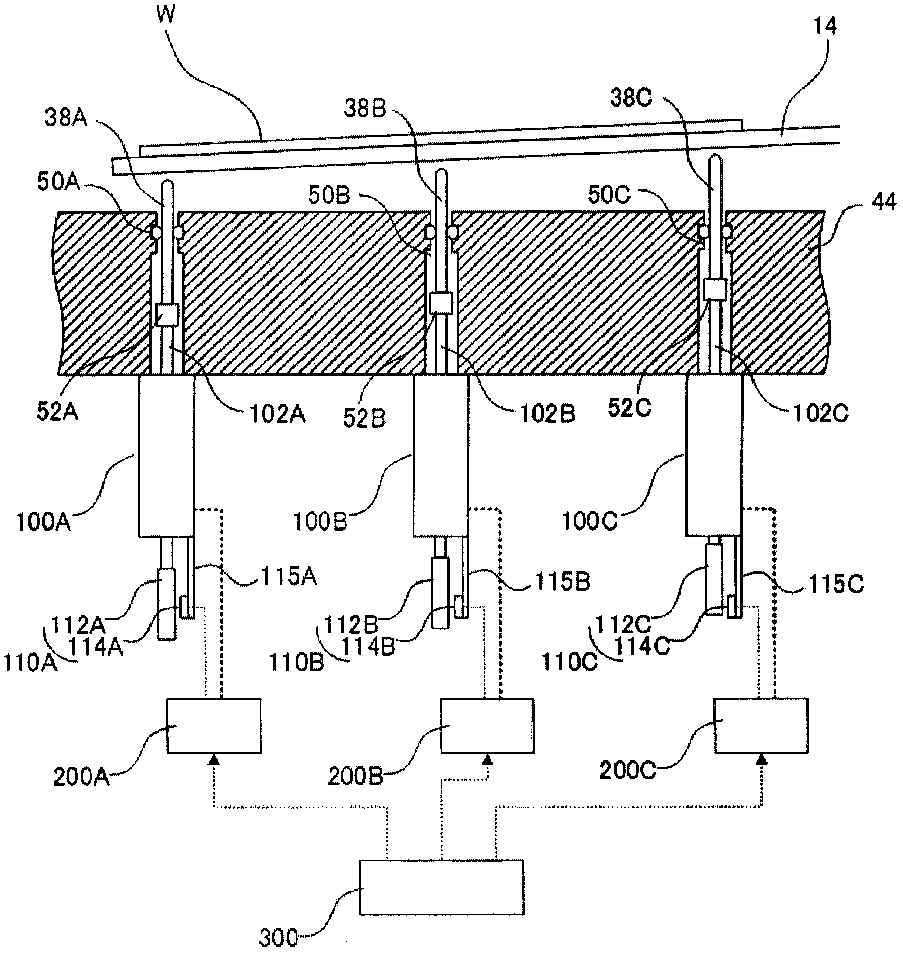
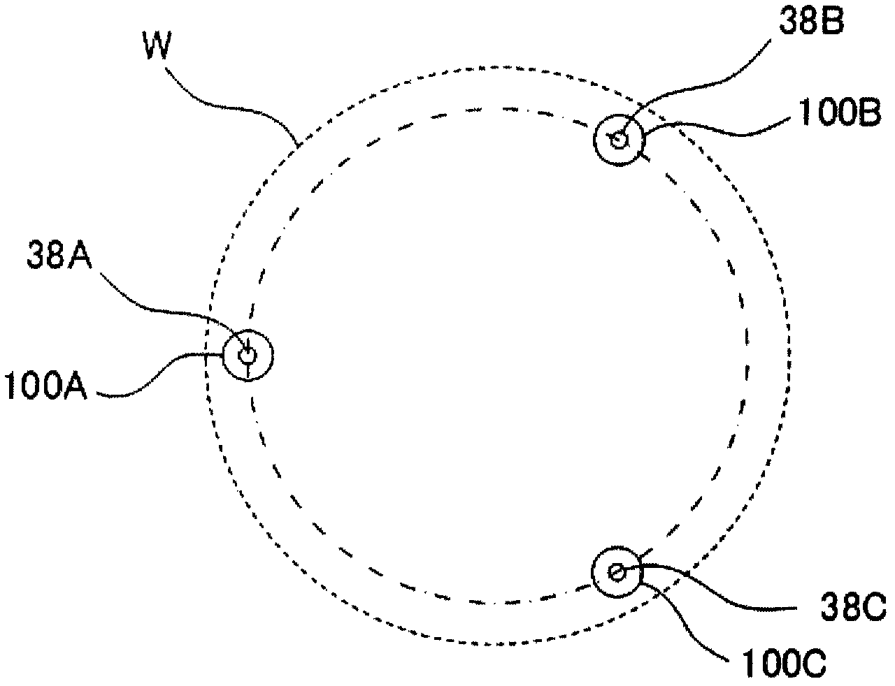
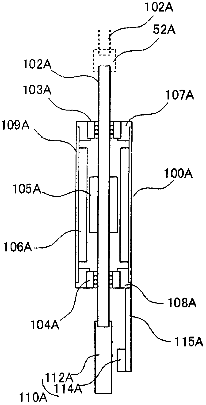
[0049] figure 1 is a schematic diagram of a support mechanism of an object to be processed (a wafer in this embodiment) in the first embodiment of the present invention, figure 2 It corresponds to the top view of the first embodiment, and is a layout diagram of lift pins and linear motors, image 3 It is a block diagram of a linear motor and a position detector. In the above figure, W is the wafer to be processed, 14 is the transfer arm, 44 is the bottom of the airtight chamber, 38A~38C are lift pins, 50A~50C are O-rings, 52A~52C are couplings, 100A~ 100C is a linear motor, 102A~102C is a movable shaft, 110A~110C is a position detector, 112A~112C is a grating scale, 114A~114C is a detection head, 200A~200C is a drive control device, 300 is a position command device, 103A 104A and 104A are linear motion guide parts, 105A is a field magnet part, 106A is an armature part, 107A and 108A are brackets, 109A is a frame, and 115A is a detection head mounting member. In addition, ...

Embodiment 2

[0062] Figure 4 It is a block diagram of the linear motor and the position detector in the second embodiment. In the figure, 116A is a scale mounting member.

[0063] The difference between the second embodiment and the first embodiment is that one end of the L-shaped grating scale mounting member 116A is mounted on the movable shaft 102A, and the grating scale 112A is mounted on the other end, while being separated from the grating scale 112A. The detection head 114A is attached to the frame body 109A with a predetermined gap. That is, the position detector 110A has a scale attachment portion 116A formed so as to be located on the outer peripheral portion of the housing 109A. That is, in contrast to the arrangement in which the position detector 110A and the linear motor 100A are coaxially arranged in the first embodiment, they are arranged in parallel in the second embodiment. By configuring in this way, it is possible to reduce the unit height of the support mechanism a...

Embodiment 3

[0065] Figure 5 It is a diagram showing the method of supporting the object to be processed (wafer) in the third embodiment, showing the flow of the method of supporting the wafer W carried by the transfer arm to the lift pins 38A to 38C. In addition, for ease of understanding and description, the lift pins 38A to 38C that are actually arranged on the circumference are arranged horizontally in a row, and the lift pins 38A to 38C are located in front of the transfer arm 14 . Figure 5 (a) is a case where the transfer arm 14 on which the wafer W is mounted enters the airtight chamber. The wafer W is tilted from the reference plane as the transfer arm 14 is deflected. In addition, before the transfer by the transfer arm 14, the inclination of the wafer at the positions of the three lift pins 38A-38C, that is, the distance from the front end of each lift pin to the bottom of the wafer, for example, is measured in advance, so that it can be used for position command. value gener...


PUM


Abstract

The invention provides a processing-object-supporting mechanism and supporting method for minimizing the configuration space of the supporting mechanism so as to benefit downsizing of the whole processing device and substantially reduce the position offset of the processing object in moving between the carrying arms. Particularly, the processing-object-supporting mechanism is characterized by having N (N is an integer of more than 3) groups of lift pins (38) in contact with the processing object (W) for supporting, a motor (100) making the lift pins (38) to lift, and a unit composed of a drive controller (200) of the drive motor (100). The drive controller (200) of each of the N groups of units is configured to control the motor (100) of each of the unit independently.

Description

technical field [0001] The present invention relates to a support mechanism, a support method, and a transfer system for a processed object used when transferring a processed object such as a wafer between a transfer arm. Background technique [0002] As a conventional support mechanism for an object to be processed, there is a mechanism in which three elevating pins for elevating the object to be processed are provided, and three elevating pins are simultaneously elevated by one elevating transmission device and an elastic hinge device (for example, Patent Document 1) . In addition, there is a mechanism in which a lift transmission device is provided on each lift pin, and the lift pins are lifted and lowered collectively by a lift control device (for example, Patent Document 2). Next, a support mechanism and a support method for a conventional object to be processed will be described. [0003] Figure 11 It is a schematic diagram showing a supporting mechanism of an objec...

Claims


Application Information

Patent Timeline
Patent Type & Authority Applications(China)
IPC IPC(8): H01L21/683H01L21/00H01L21/677
CPCH01L21/68742H01L21/683H01L21/68714
Inventor 鹿山透野口忠隆丰田昭仁草间义裕
Owner YASKAWA DENKI KK
Why Eureka
Try Eureka