Electromagnetic clutch

An electromagnetic clutch and machine technology, applied in clutches, magnetic drive clutches, non-mechanical drive clutches, etc., can solve the problem of inability to reduce the outer diameter of the second rotating body, reduce the adsorption area of ​​the armature plate, increase the power consumption of the electromagnetic clutch, etc. question

Inactive Publication Date: 2006-10-04
SANDEN CORP
View PDF0 Cites 6 Cited by
  • Summary
  • Abstract
  • Description
  • Claims
  • Application Information

AI Technical Summary

Problems solved by technology

In addition, the outer diameter of the second rotating body cannot be reduced due to the need to install each leaf spring
Therefore, it is not possible to reduce the inner diameter of the armature plate in order to expand the above-mentioned adsorption area.
In addition, the enlargement of the outer diameter of the armature plate or the strengthening of the magnetic force of the electromagnetic coil will lead to an increase in the size of the electromagnetic clutch and an increase in power consumption.

Method used


Image

  • Electromagnetic clutch
  • Electromagnetic clutch
  • Electromagnetic clutch

Examples


Embodiment Construction

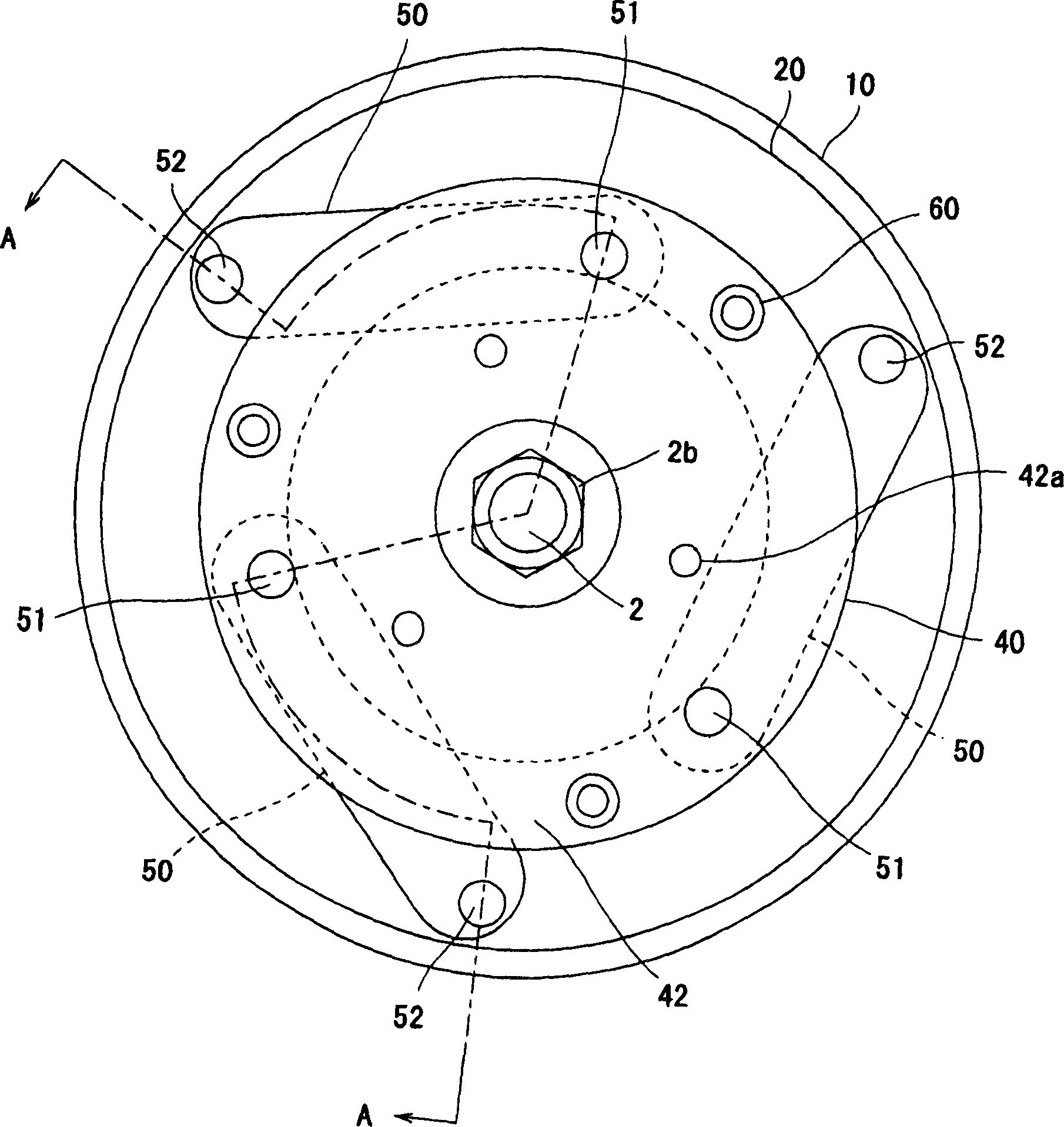
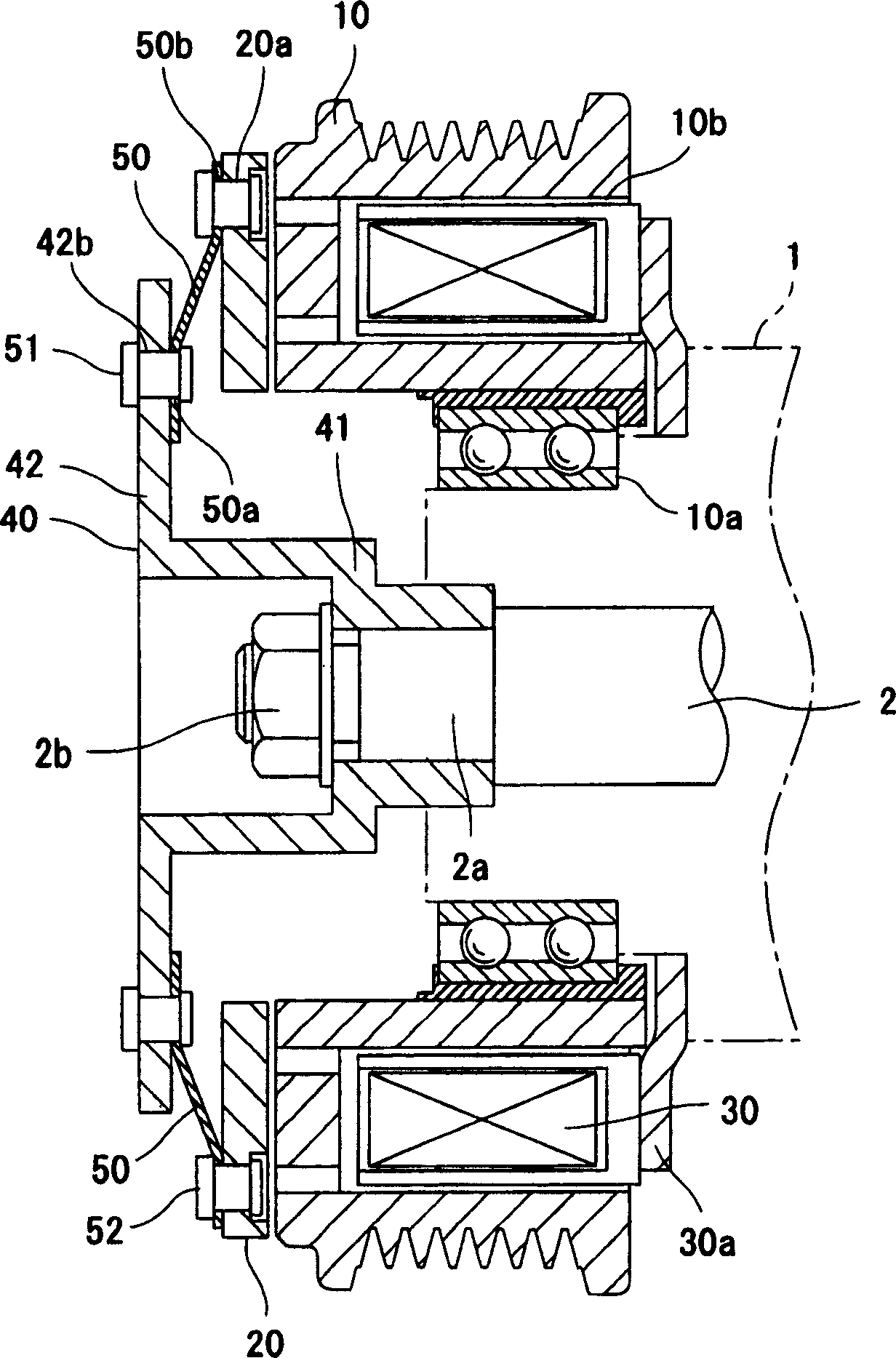
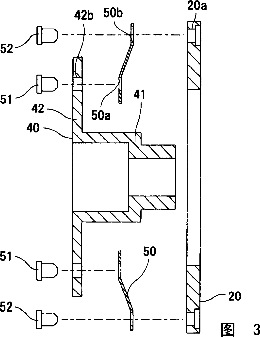
[0021] Figure 1 to Figure 4 An embodiment of the present invention is shown. figure 1 is the front view of the electromagnetic clutch, figure 2 for figure 1 Figure 3 is a side sectional view of the armature plate, the second rotating body and each leaf spring before assembly, Figure 4 It is a side cross-sectional view showing a state in which an armature plate with a small inner diameter is assembled with a second rotating body and each leaf spring.

[0022] The electromagnetic clutch of this embodiment is provided with: the first rotating body 10 is transmitted with the power from the engine not shown in the figure; Connected to the first rotating body 10; the electromagnetic coil 30 is used to attract the armature plate 20 to the first rotating body 10 side; the second rotating body 40 has another armature plate 20 with a predetermined distance in the axial direction. An extension part 42 provided with facing end faces is connected to the rotating shaft 2 of the compr...


PUM


Abstract

In this electromagnetic clutch, only each of the plate springs is connected to the second rotor by first connecting members. Therefore, each of the first holes of the plate springs is accurately positioned to the position of each of the second holes of the extended portion. That is, it is not necessary to provide a useless gap between the first connecting members and the each of the holes. Also, the extended portion of the second rotor is opposed to the armature plate in the axial direction. Therefore, the inner diameter of the armature plate can be formed small irrespective of the extended portion.

Description

technical field [0001] The present invention relates to an electromagnetic clutch used, for example, to transmit power from a vehicle drive source to a compressor of a vehicle air-conditioning device. Background technique [0002] A generally known electromagnetic clutch includes: a first rotating body that is rotated by external power; an armature plate that is arranged to face the first rotating body in the axial direction, and one end surface can be in contact with the first rotating body; The electromagnetic coil is used to attract the armature plate to the side of the first rotating body; the second rotating body is formed so that the outer peripheral surface faces the inner peripheral surface of the armature plate in the radial direction, and rotates together with the driven shaft of the driven side machine a plurality of leaf springs arranged between the armature plate and the second rotating body; a plurality of first rivets respectively connecting one end side of ea...

Claims


Application Information

Patent Timeline
Patent Type & Authority Applications(China)
IPC IPC(8): F16D27/112
CPCF16D27/112F16D2027/007
Inventor 松村知则一之濑启一
Owner SANDEN CORP
Why Eureka
Try Eureka