Radiation tomography apparatus

a tomography and radiography technology, applied in tomography, instruments, patient positioning for diagnostics, etc., can solve the problems of /b> greatly increasing the manufacturing cost, affecting the cost of radiation tomography apparatus, and high price of tomography tomography apparatus, so as to improve the spatial resolution and detection sensitivity of radiation, and the effect of low pri

Inactive Publication Date: 2012-01-05
SHIMADZU CORP
View PDF17 Cites 11 Cited by
  • Summary
  • Abstract
  • Description
  • Claims
  • Application Information

AI Technical Summary

Benefits of technology

[0016]This invention includes at least two detector rings for detecting radiation from the subject. One of the detector rings is the first detector ring having a sufficient internal diameter to introduce shoulders of the subject, and the other is the second detector ring having a smaller internal diameter than the first detector ring. The subject has a largest width at the shoulder thereof. Consequently, it is not necessary for the detector ring to have a large internal diameter throughout thereof. The detector ring may have a region with a smaller internal diameter independently of the shoulder of the subject. In so doing, the radiation detectors forming the detector ring may be suppressed in number, which may provide radiation tomography apparatus of low price.
[0017]Moreover, a smaller diameter of the detector ring may result in improved spatial resolution and detection sensitivity of radiation. The longer the distance becomes between the radiation detector and a generation source of radiation, the less the dose of radiation reaches the radiation detector. Consequently, in order to improve detection sensitivity, a smaller internal distance between the subject and the radiation detector and a smaller diameter of the detector ring are preferable. Moreover, an annihilation radiation pair is generated through collision of a positron with an electron. Here, kinetic energy of the positron and the electron is conserved in the paired radiation. Consequently, each of the annihilation radiation pair travels in a direction slightly deviating from a straight angle opposite to each other. Accordingly, the incident position in the detector ring deviates from an ideal position. The larger internal diameter the detector ring has, the larger an amount of deviation of the incident position in the detector ring becomes due to deviation in the travel direction of the annihilation radiation pair. Consequently, the radiation tomography apparatus has poor spatial resolution. That is, the detector ring having a smaller internal diameter is preferable for provision of the radiation tomography apparatus of high spatial resolution. According to the configuration of this invention, both two effects mentioned above will be produced.
[0018]According to this configuration, the subject may reliably be inserted into inside of the detector rings. Specifically, the bed moves in a direction from the first detector ring toward the second detector ring when the bed is inserted into inside of both the detector rings. That is, the shoulder o...

Problems solved by technology

The conventional configuration as above, however, has the following problem.
Specifically, adaptation of the conventional configuration directly to radiation tomography apparatus for total body inspection may lead to radiation tomography apparatus of high price.
Accordingly, the detector ring 53 greatly increases in manufacturing cost.
The cost of radiation tomography apparatus is largely influenced by the number of radiation detector...

Method used


Image

  • Radiation tomography apparatus
  • Radiation tomography apparatus
  • Radiation tomography apparatus

Examples


embodiment 1

[0060]

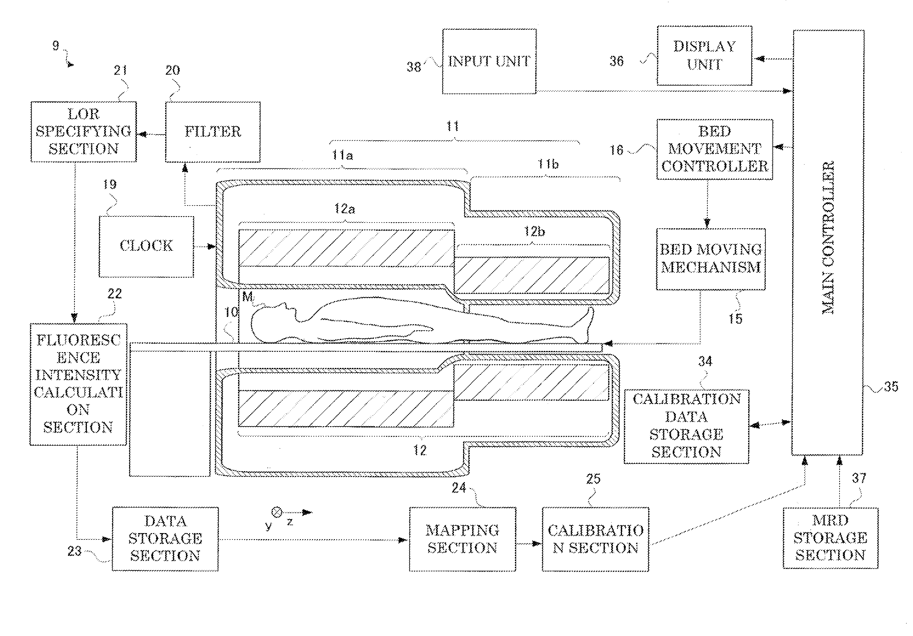
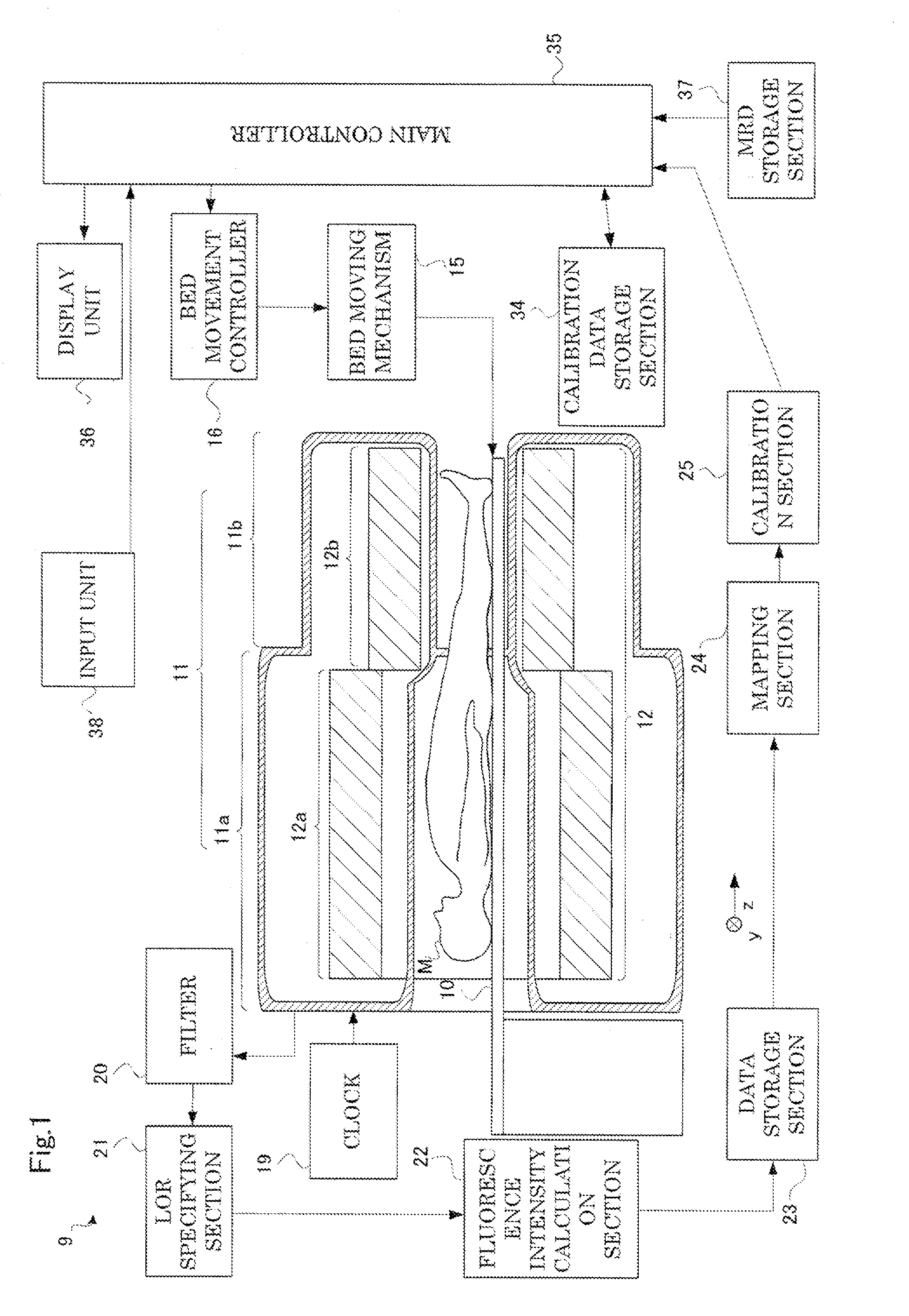
[0061]Each embodiment of radiation tomography apparatus according to Embodiment 1 will be described hereinafter with reference to the drawings. FIG. 1 is a functional block diagram showing a configuration of radiation tomography apparatus according to Embodiment 1. As shown in FIG. 1, the radiation tomography apparatus 9 according to Embodiment 1 includes a bed 10 for placing a subject M on the back thereof, and a gantry 11 with a through hole for surrounding the subject M. The bed 10 is provided as to pass through an opening of the gantry 11. The bed 10 freely moves in and out along a direction where the opening of the gantry 11 extends (i.e., a z-direction.) A bed moving mechanism 15 moves the bed 10 as above. A bed movement controller 16 controls the bed moving mechanism 15.

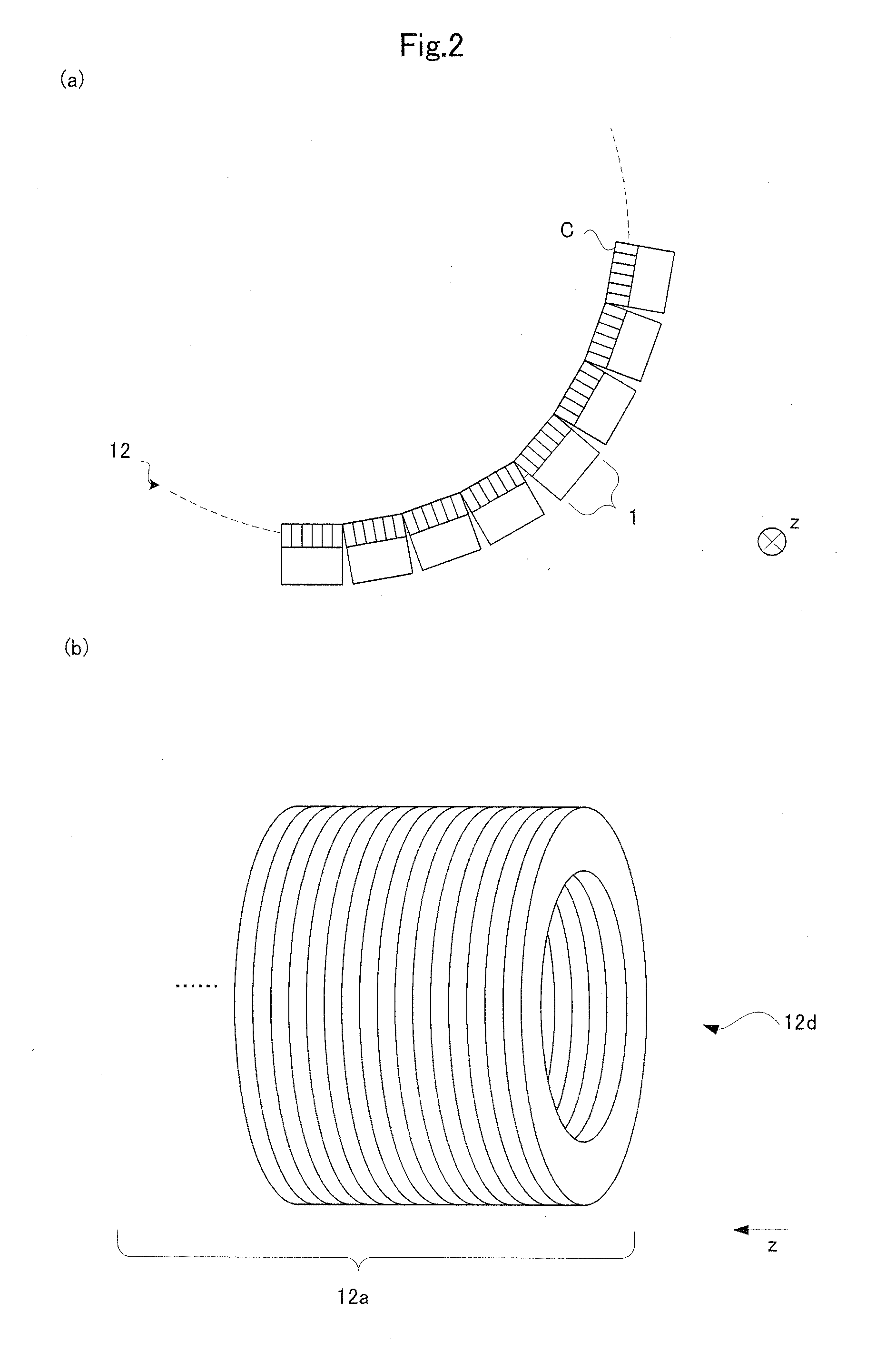
[0062]The gantry 11 includes a detector ring 12 inside thereof that detects annihilation gamma-ray pairs from the subject M. The detector ring 12 is tubular and extends in a body axis direction z of the ...

embodiment 2

[0091]Next, description will be given of a PET / CT device according to Embodiment 2. The PET / CT device includes the radiation tomography apparatus (PET device) 9 described in Embodiment 1 and a CT device for generating a sectional image using X-rays, and is medical apparatus that allows generation of a composite image having superimposed sectional images acquired in both devices.

[0092]Here, description will be given of a configuration of the PET / CT device according to Embodiment 2. The radiation tomography apparatus (PET device) 9 described in Embodiment 1 may be used for the PET / CT device according to Embodiment 2. Consequently, description will be given of the CT device as a characteristic portion in Embodiment 2. As shown in FIG. 7, the CT device 8 has a gantry 45. The gantry 45 is provided with an opening that extends in the z-direction with a bed 10 inserted therein. Here, the CT device 8 is provided on the first detector ring 12a side of the radiation tomography apparatus 9, an...


PUM


Abstract

This invention has one object is to provide radiation tomography apparatus that allows production with low price through suppression in number of radiation detectors to be mounted. One of the detector rings in this invention is a first detector ring having a sufficient internal diameter to introduce shoulders of the subject M, and the other is a second detector ring having a smaller internal diameter than the first detector ring. In so doing, the radiation detectors forming the detector ring may be suppressed in number, which may provide radiation tomography apparatus of low price. Moreover, a smaller diameter of the detector ring may result in improved spatial resolution and detection sensitivity of radiation.

Description

TECHNICAL FIELD[0001]This invention relates to radiation tomography apparatus that images radiation emitted from a subject. Particularly, this invention relates to radiographic apparatus having a field that is wide enough to image a body portion of the subject at one time.BACKGROUND ART[0002]In medical fields, radiation emission computed tomography (ECT: Emission Computed Tomography) apparatus is used that detects an annihilation radiation (for example, gamma rays) pair emitted from radiopharmaceutical that is administered to a subject and is localized to a site of interest for acquiring sectional images of the site of interest in the subject showing radiopharmaceutical distributions. Typical ECT equipment includes, for example, a PET (Positron Emission Tomography) device and an SPECT (Single Photon Emission Computed Tomography) device.[0003]A PET device will be described by way of example. The PET device has a detector ring with block radiation detectors arranged in a ring shape. T...

Claims


Application Information

Patent Timeline
IPC IPC(8): G01T1/161A61B6/04
CPCG01T1/2985A61B6/032A61B6/037G01T1/1611A61B6/10A61B6/4417A61B6/04
Inventor INOUE, YOSHIHIROAMANO, MASAHARUTANAKA, KAZUMIMIZUTA, TETSUROOHTANI, ATSUSHI
Owner SHIMADZU CORP
Why Eureka
Try Eureka