Pattern forming apparatus and pattern forming method
A pattern and axis direction technology, applied in the field of pattern forming device and pattern formation, can solve the problems of large position deviation and inability to perform alignment on one end side, etc., and achieve the effect of small position deviation
- Summary
- Abstract
- Description
- Claims
- Application Information
AI Technical Summary
Problems solved by technology
Method used
Image
Examples
no. 1 approach
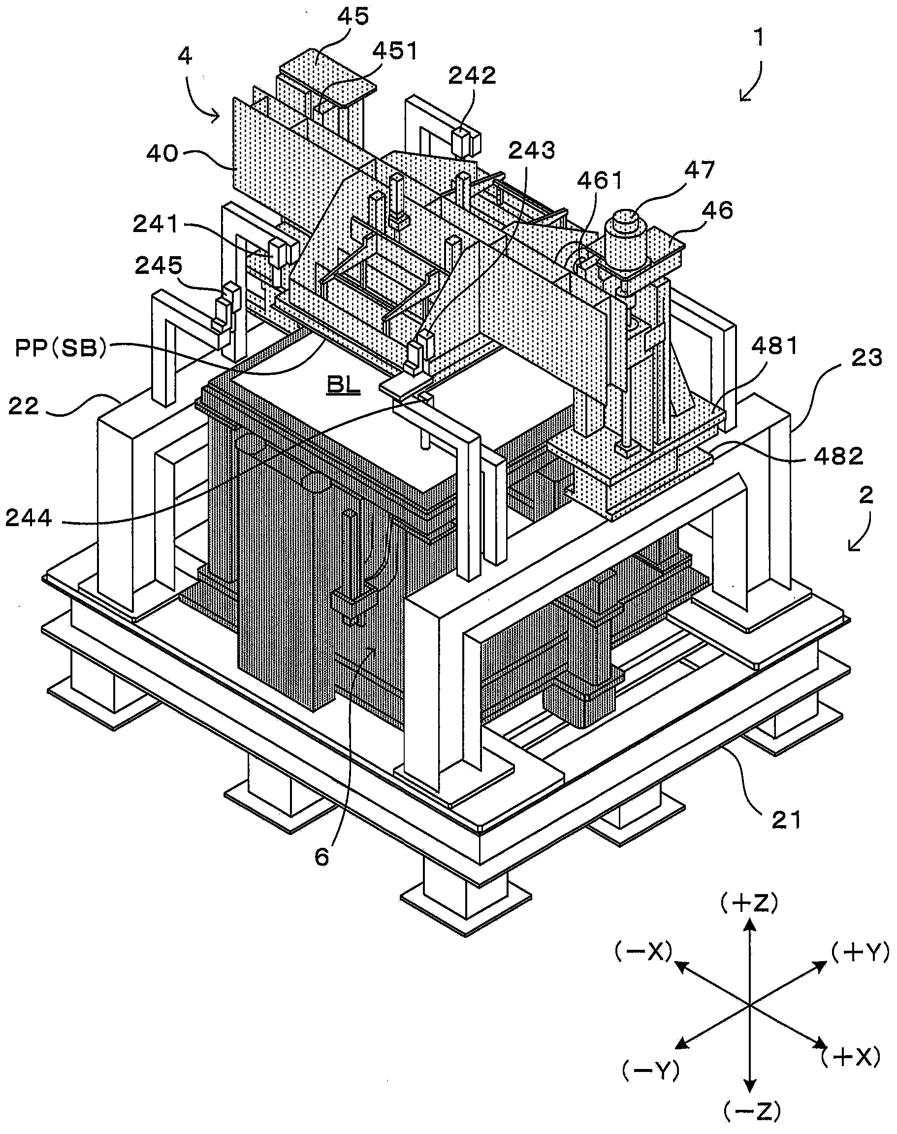
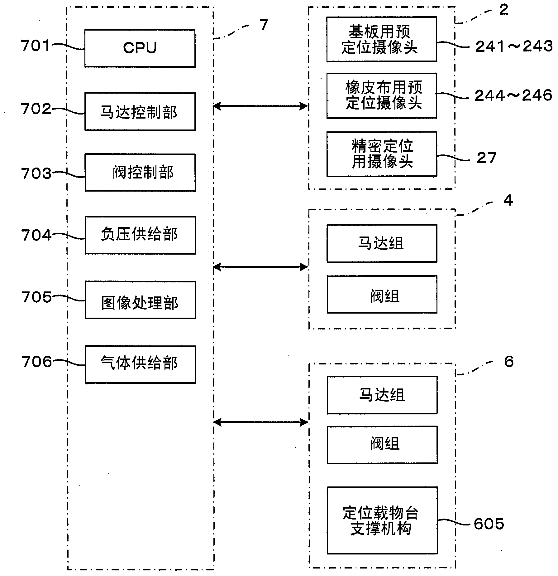
[0065] figure 1 It is a perspective view which shows 1st Embodiment of the pattern forming apparatus of this invention. in addition, figure 2 is a block diagram showing a control system of the pattern forming apparatus. In addition, in figure 1 In , the state in which the external cover is removed is shown in order to show the internal structure of the device. In order to unify the direction in each figure, such as figure 1 Set the XYZ orthogonal coordinate axes as shown on the lower right. Here, the XY plane represents a horizontal plane, and the Z axis represents a vertical axis. More specifically, the +Z direction indicates a vertically upward direction. The front surface direction when viewed from the device is the -Y direction, and operations to access the device from the outside, including loading and unloading items, are performed along the Y-axis direction.
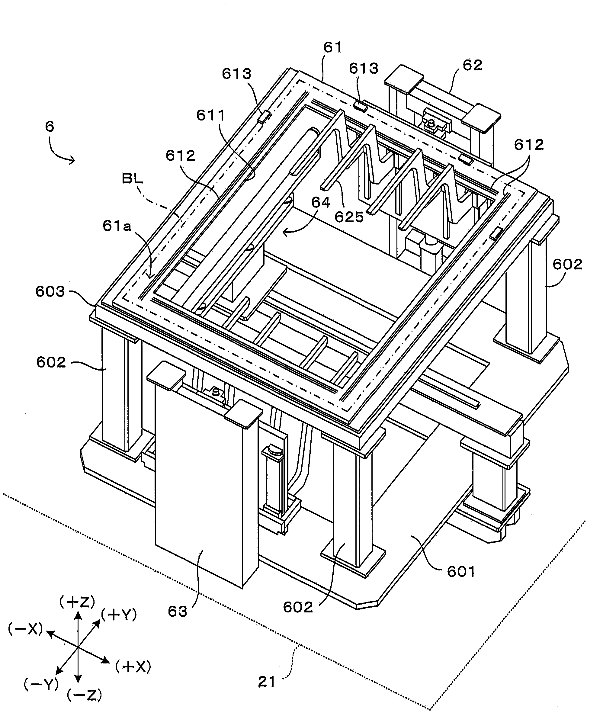
[0066] The pattern forming apparatus 1 is configured such that an upper stage unit 4 and a lower stage ...
no. 2 approach
[0159] Next, a second embodiment of the pattern forming apparatus of the present invention will be described. The pattern forming apparatus of the second embodiment is different from the pattern forming apparatus 1 of the above-mentioned first embodiment only in a part of the structure of the loading and unloading stage portion. On the other hand, other structures in the first embodiment, that is, the main frame 2, the upper stage portion 4, and the control unit 7 can basically be directly used as the main frame, the upper stage portion, and the control unit in the second embodiment. . Therefore, the following description will focus on the differences from the first embodiment, especially the structure and operation of the loading object stage. In addition, the same code|symbol is attached|subjected to the same structure as 1st Embodiment, and description is abbreviate|omitted.
[0160] Figure 17 It is a figure which shows the main part of 2nd Embodiment of the pattern for...
no. 3 approach
[0192] Next, a third embodiment of the pattern forming apparatus of the present invention will be described. The pattern forming apparatus of the third embodiment is different from the pattern forming apparatus 1 of the above-mentioned first embodiment only in a part of the structure of the loading and unloading stage portion. On the other hand, other structures in the first embodiment, that is, the main frame 2, the upper stage portion 4, and the control unit 7 can basically be directly used as the main frame, the upper stage portion, and the control unit, etc. in the third embodiment. . Therefore, the following description will focus on the differences from the first embodiment, especially the structure and operation of the loading object stage. In addition, the same code|symbol is attached|subjected to the same structure as 1st Embodiment, and description is abbreviate|omitted.
[0193] Figure 21 It is a figure which shows the main part of 3rd Embodiment of the pattern ...
PUM
 Abstract
Description
Claims
Application Information
 - R&D
- Intellectual Property
- Life Sciences
- Materials
- Tech Scout
- Unparalleled Data Quality
- Higher Quality Content
- 60% Fewer Hallucinations
Browse by: Latest US Patents, China's latest patents, Technical Efficacy Thesaurus, Application Domain, Technology Topic, Popular Technical Reports.
© 2025 PatSnap. All rights reserved.Legal|Privacy policy|Modern Slavery Act Transparency Statement|Sitemap|About US| Contact US: help@patsnap.com


