Method and apparatus for image forming

a technology of image forming and apparatus, applied in the field of image forming technology, can solve the problems of increasing circuit scale, increasing cost, and reducing the quality of formed images, so as to reduce the shift of position and reduce the cost

Inactive Publication Date: 2007-10-02
CANON KK
View PDF9 Cites 7 Cited by
  • Summary
  • Abstract
  • Description
  • Claims
  • Application Information

AI Technical Summary

Benefits of technology

[0012]The present invention arranges matters so as to select the preferable light emission timing according to differences in light beam intensity and resolution, and therefore light intensity control for changing the light intensity when the light beam scans the photosensitive drum and when the light beam scans the photo detectors can be eliminated. In addition, cost can be reduced while reducing shift of the position at which an image starts to be drawn.

Problems solved by technology

Moreover, this shift is expressed as color shift, and thus seriously degrades the quality of the formed image.
However, since this method requires two circuits, i.e., one circuit that sets the light intensity when scanning the photosensitive drum and another circuit that sets the light intensity when scanning the photo detectors, circuit scale increases, leading unavoidably to an increase in cost.

Method used


Image

  • Method and apparatus for image forming
  • Method and apparatus for image forming
  • Method and apparatus for image forming

Examples


first embodiment

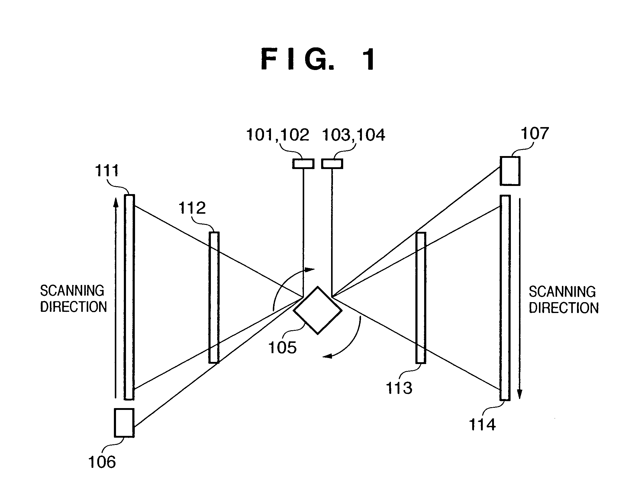
[0031]FIG. 1 is a diagram showing an example of an optical scanning apparatus of a color image forming apparatus capable of adapting the invention according to the present embodiment. Laser beams emitted from a yellow image forming semiconductor laser (hereinafter the yellow laser) 101, a magenta image forming semiconductor laser (hereinafter the magenta laser) 102, a cyan image forming semiconductor laser (hereinafter the cyan laser) 103, and a black image forming semiconductor laser (hereinafter the black laser) 104, respectively, are collected into parallel rays by a collimator lens, not shown, and scanned at equal angular speeds upon reflection by a polygon mirror 105 rotating at a constant rpm.

[0032]The laser beams reflected by the polygon mirror 105 pass through an fθ lens, not shown, are reflected by a yellow laser reflecting mirror 111, a magenta laser reflecting mirror 112, a cyan laser reflecting mirror 113 and a black laser reflecting mirror 114, respectively, and directe...

second embodiment

[0051]In the present embodiment, a description is given of an example of the calculation of the preferable light emission timing data at each light intensity.

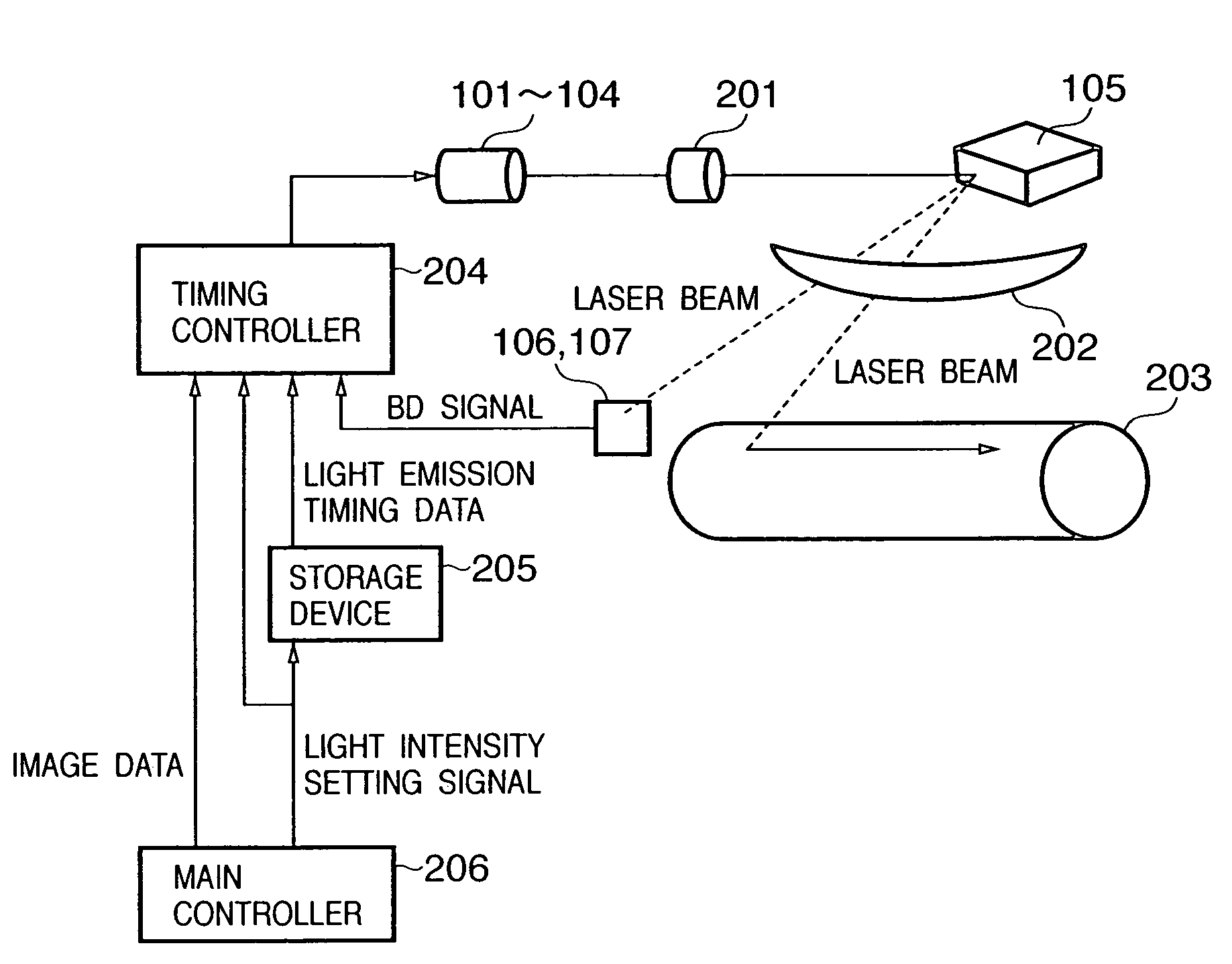
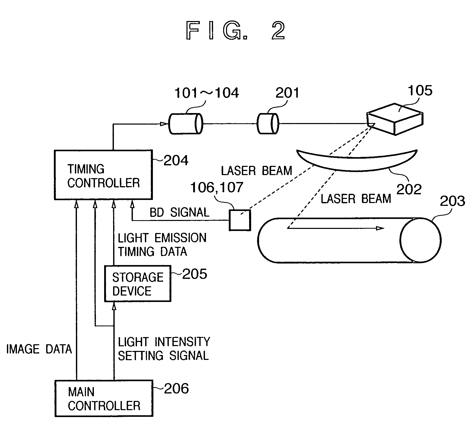
[0052]FIG. 8 is a diagram showing an example of an image forming apparatus according to the present embodiment. Structures that are identical to those already described are allocated identical reference numerals, and a description thereof is omitted here.

[0053]A printer controller 801 is an image processing apparatus that performs image processing on image data input from an 806 optical sensor controller. Reference numeral 802 is an engine controller, which is a control device that controls an image-forming engine 803 based on image signals output from the printer controller 801. Included in the image-forming engine 803 are the lasers 101-104, the photosensitive drum 203, and, not shown, a fixing apparatus, a recording paper transport mechanism and the like. Included in the engine controller 802 are the above-described timing c...

third embodiment

[0071]In the present embodiment, an example of a specific method for determining the light emission timing is shown. FIG. 13 is a diagram showing an example of a table showing the relation between light intensity settings and light emission timing data according to the present embodiment. The horizontal axis shows the light intensity settings and the vertical axis shows the light emission timing. In the example shown in the diagram, the light emission timing data is set at t1 seconds for light intensity A and at t2 seconds for light intensity B. This light emission timing data t1, t2 indicates the light emission starting time of the laser beams using the respective BD signal pulse rise times as references.

[0072]By referring to the table as described, a unique light emission timing can be determined from a given light intensity. The table can be stored in the storage device 205. The storage device 205 outputs light emission timing data corresponding to the light intensity setting sig...


PUM


Abstract

An image forming apparatus in which the intensity of a light beam used to form a latent image is switched in response to a change in resolution. A laser emits a light beam for forming a latent image on a photosensitive drum. A polygon mirror scans the emitted light beam. BD sensors detect the scanned beam. A timing controller selects the preferable timing from a storage device table according to the intensity of the light beam or the resolution when controlling the light emission timing of the lasers in response to a detection of timing of the detected light beam.

Description

FIELD OF THE INVENTION[0001]This invention relates to an image forming technology that forms an image using a light beam such as a laser beam.BACKGROUND OF THE INVENTION[0002]Conventionally, an image forming apparatus is known that, by switching resolution, can form a high resolution image (for example, of 1200 dpi) and a low resolution image (for example, of 600 dpi).[0003]In a case in which the rotation speed of a polygon mirror is the same when forming an image of 600 dpi and when forming an image of 1200 dpi, the rotation speed of a photosensitive drum at 1200 dpi is set at ½ that at 600 dpi. In addition, when the integrated light intensity of the laser scanning the photosensitive drum is the same in both 600 dpi and 1200 dpi directions, the laser light intensity at 1200 dpi is set at half that at 600 dpi, and furthermore, it is necessary to double the frequency of the image clock that drives the laser. By these adjustments, a 1200 dpi image is formed in both the main scanning d...

Claims


Application Information

Patent Timeline
Patent Type & Authority Patents(United States)
IPC IPC(8): B41J2/435B41J2/47B41J2/44G06K15/12H04N1/113H04N1/23
CPCG06K15/1219G02B26/127
Inventor SOBUE, FUMITAKATAIRA, MASAYOSHIKAKUTANI, TOSHIFUMISUGIURA, TAKASHITAKATA, SHINICHIOKA, YUSHINAGATA, NAOHISA
Owner CANON KK
Why Eureka
Try Eureka