Insulation displacement contact and electric connector using the same

a technology of displacement contact and electric connector, which is applied in the direction of contact members penetrating/cutting insulation/cable strands, application, coupling device connections, etc., can solve the problems of inability to provide bent portions, inability to provide spatial space for providing bent portions, and inability to reduce stress concentration. , to achieve the effect of improving the resilience deformation range, reducing the stress concentration, and improving the reliability of the electric connection

Active Publication Date: 2006-06-06
JST MFG CO LTD
View PDF13 Cites 12 Cited by
  • Summary
  • Abstract
  • Description
  • Claims
  • Application Information

AI Technical Summary

Benefits of technology

[0022]According to the present invention, each of the pair of resilient contact pieces has a tapering portion of which width is gradually narrowed in the direction toward the contact portion. Accordingly, when a counterpart contact is held or nipped by and between the pair of contact portions, the stress is dispersed at the tapering portions. Accordingly, as compared with the arrangement in which each of the resilient contact pieces is made of a uniform-width plate-like body, the stress concentration can be restrained, and the entire tapering portions are therefore resiliently deformed as bent, thus increasing the resilient deformation range of the resilient contact pieces in their entirety.
[0023]Accordingly, even though a counterpart contact is inserted between the contact portions in the state where an insulated wire is inserted (press-fitted) into the slot formed by the pair of insulation displacement blades to rotate the resilient contact pieces to narrow (or eliminate) the gap between the contact portions, the amount of deformation of the resilient contact pieces is restrained or prevented from exceeding the resilient deformation range and then entering the plastic deformation range. Accordingly, even though the insulation displacement contact is extremely miniaturized in size, it is possible to assure the state where the contact portions come in resilient contact with the counterpart contact, thus improving the reliability of the electric connection.
[0024]Further, the resilient contact pieces are formed as connected to the outer sides of the insulation displacement blades. This prevents the entire height of the insulation displacement contact from being high. This consequently prevents the entire height of the electric connector from being high.
[0025]Thus, there can be achieved an electric connector extremely miniaturized in size and low in height, yet capable of assuring a high reliability of electric connection.

Problems solved by technology

Accordingly, the insulation displacement connector is inevitably extremely miniaturized in size; therefore, has no spatial room for providing bent portions at the tips of the contact pieces as the insulation displacement contact disclosed in the above-mentioned Publication.
However, for an extremely miniaturized insulation displacement contact in which the contact pieces cannot be provided at their tips with bent portions, the insertion of the base connector contact has to rely solely on the resilient deformation of the contact pieces in their entirety.
It is therefore not possible that the contact portions come in resilient contact with the base connector contact.
This may possibly injure the reliability of electric connection therebetween.
This results in increase in the entire height of the insulation displacement connector.
This goes against the market demand for an electric connector to be used in a small-size electronic device.

Method used


Image

  • Insulation displacement contact and electric connector using the same
  • Insulation displacement contact and electric connector using the same
  • Insulation displacement contact and electric connector using the same

Examples


Embodiment Construction

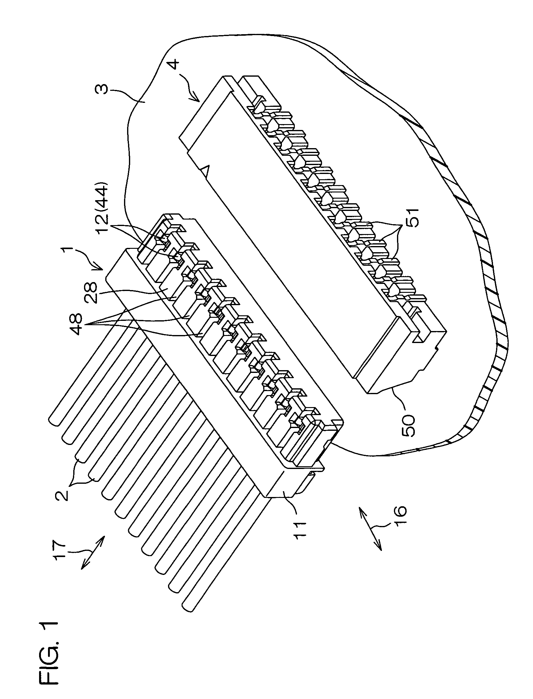
[0036]FIG. 1 is a perspective view illustrating how to use an electric connector according to a preferred embodiment of the present invention. The electric connector 1 according to this embodiment is a wire-side connector connected to a plurality of insulated wires 2. This wire-side connector 1 can be connected, for example, to a board-side connector (base connector) 4 surface-mounted on a printed circuit board 3. When the wire-side connector 1 is connected to the board-side connector 4, the insulated wires 2 are electrically connected to the printed circuit board 3.

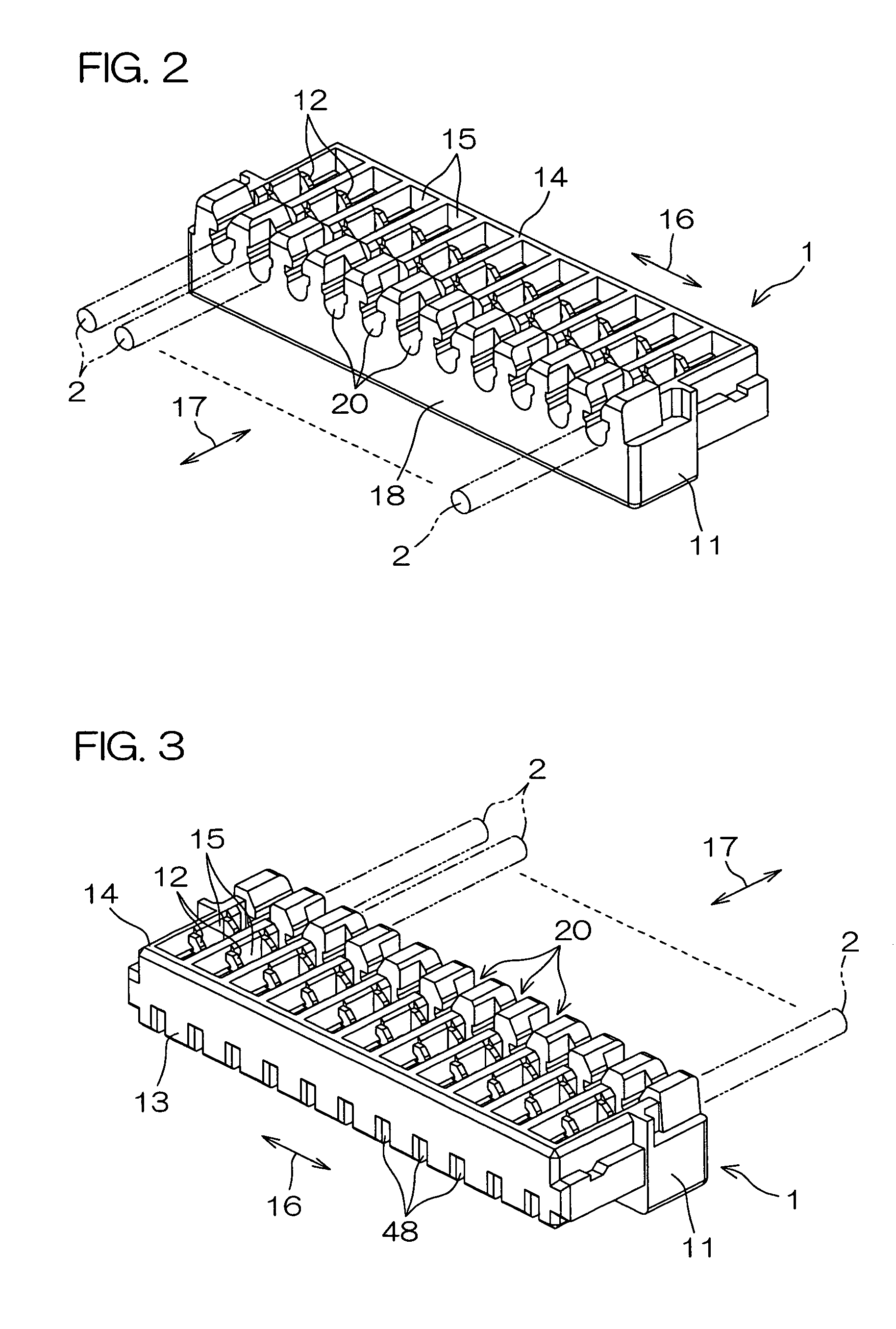
[0037]FIG. 2 and FIG. 3 are perspective views of the wire-side connector 1 with its actual upside turned down. FIG. 2 shows the wire-side connector 1 as viewed from the rear side to which the insulated wires 2 are to be connected, while FIG. 3 shows the wire-side connector 1 as viewed from the front side (from the board-side connector 4).

[0038]This wire-side connector 1 comprises a housing 11 made of a synthetic resin mo...


PUM


Abstract

An insulation displacement contact includes a pair of insulation displacement blades and a pair of resilient contact pieces. The pair of insulation displacement blades are opposite to each other with their bases connected to each other such that there is formed, by their inner sides, a slot for receiving an insulated wire of which core wire portion is covered with an insulation. The pair of insulation displacement blades are arranged such that when the insulated wire is inserted into the slot, the insulation is cut and the core wire portion comes in press-contact with the insulation displacement blades. Each of the pair of resilient contact pieces is made of a plate member which is connected to the outer side of each insulation displacement blade, which extends toward the side opposite of the inlet of the slot up to a position exceeding the base of each insulation displacement blade, which has a contact portion for holding or nipping a mating contact at a position opposite of the slot inlet with respect to the base of each insulation displacement blade, and which has, between the connection portion connected to the outer side of each insulation displacement blade and the contact portion, a tapering portion of which width is gradually narrowed in the direction toward the contact portion.

Description

BACKGROUND OF THE INVENTION[0001]1. Field of the Invention[0002]The present invention relates to an insulation displacement contact and an electric connector (insulation displacement connector) using the same.[0003]2. Description of Related Art[0004]A connector to be attached to an insulated wire has a resin housing and a contact (terminal metal fitting) secured to the housing. An insulation displacement contact has the structure in which a slot for holding the core wire portion of an insulated wire is formed between a pair of insulation displacement blades for breaking up the insulation of the insulated wire. When such an insulation displacement contact is used, the contact and the core wire portion of the insulated wire can be electrically connected to each other merely by pushing the insulated wire into the slot of the insulation displacement contact. A connector using such an insulation displacement contact is called an insulation displacement connector.[0005]For example, as dis...

Claims


Application Information

Patent Timeline
Patent Type & Authority Patents(United States)
IPC IPC(8): H01R4/24H01R4/00H01R4/18H01R9/03H01R11/20H01R12/30H01R12/71H01R12/79H01R43/16
CPCH01R4/2454H01R12/79H01R12/716H01R43/16H01R2201/16A01K61/65Y02P60/60
Inventor HIRAMOTO, MASAYUKISUYAMA, TAKASHINAKASHIMA, TERUMI
Owner JST MFG CO LTD
Why Eureka
Try Eureka