Transparent combustion chamber with square interior passage

A combustion chamber and inner channel technology, which is used in jet propulsion devices, rocket engine devices, machines/engines, etc., can solve the problems of real flow field influence, combustion chamber pressure distortion, and channels that cannot be well flushed, and can be disassembled. Convenient and fast, good sealing effect, and the effect of protecting quartz glass

Inactive Publication Date: 2011-05-18
BEIHANG UNIV
View PDF6 Cites 32 Cited by
  • Summary
  • Abstract
  • Description
  • Claims
  • Application Information

AI Technical Summary

Problems solved by technology

[0003] Domestic research on the flow display of the injector hot test test is mostly carried out in the atmospheric environment. The oxygen in the atmospheric environment will have a greater impact on the combustion flame, and the ambient pressure is far lower than the pressure in the actual engine. The results are quite different from the actual ones; in foreign countries, most of the research on the flow display of the hot test of the injector is carried out in the transparent combustion chamber. The circular inner channel cannot be well aligned, which has a great impact on the real flow field. From the perspective of the designed transparent combustion chamber structure, the system is complicated, and nitrogen or hydrogen is often used to feed the quartz glass on the transparent combustion chamber. Film cooling protection causes the measured combustion chamber pressure to be distorted, and the temperature measurement of the wall surface is not carried out at the same time when the combustion flow field display test is carried out, which is not conducive to linking the results measured by traditional measurement techniques with the results obtained by optical measurement methods

Method used


Image

  • Transparent combustion chamber with square interior passage
  • Transparent combustion chamber with square interior passage
  • Transparent combustion chamber with square interior passage

Examples


Embodiment Construction

[0034] The present invention will be further described in detail with reference to the accompanying drawings and embodiments.

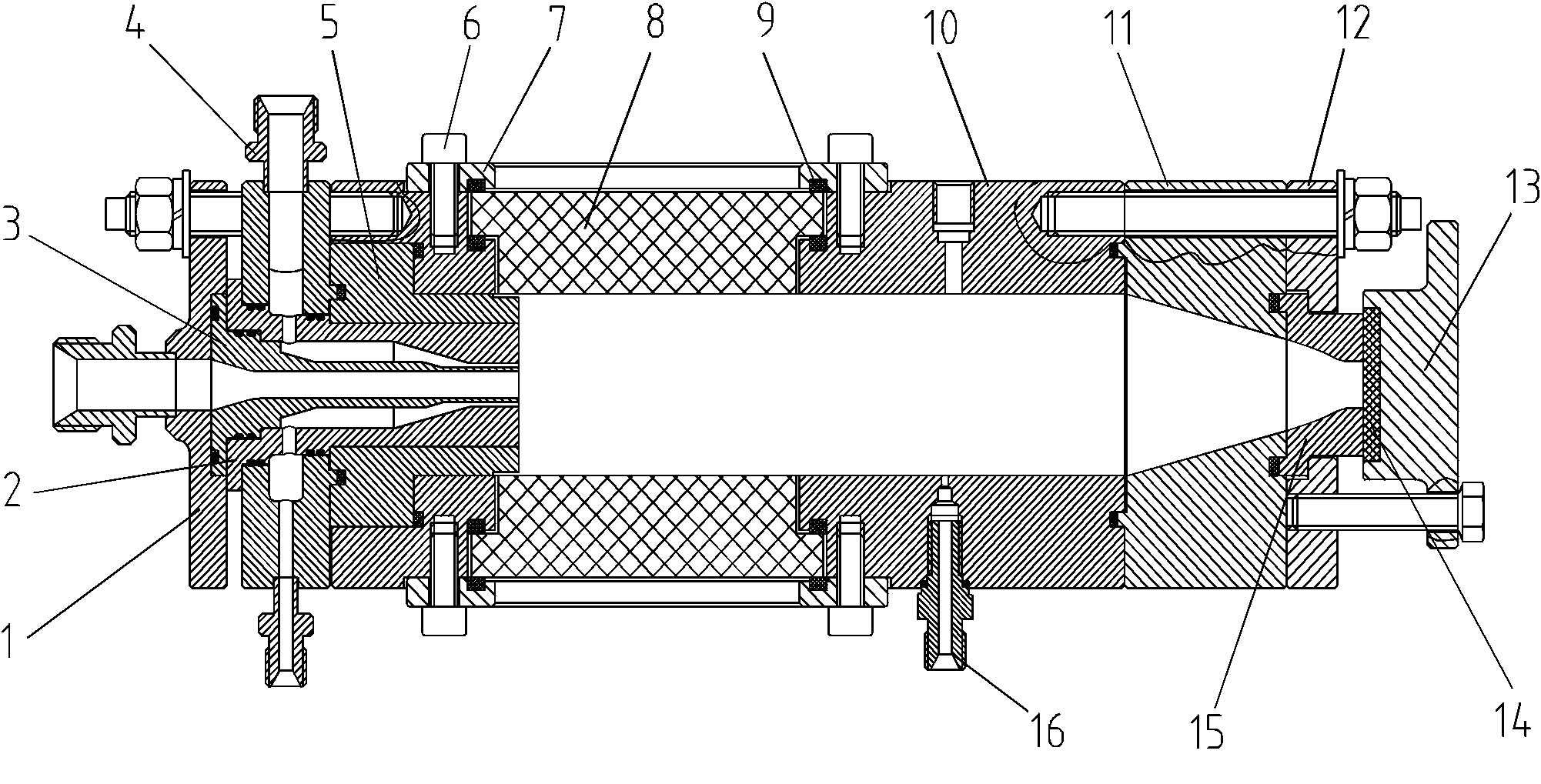
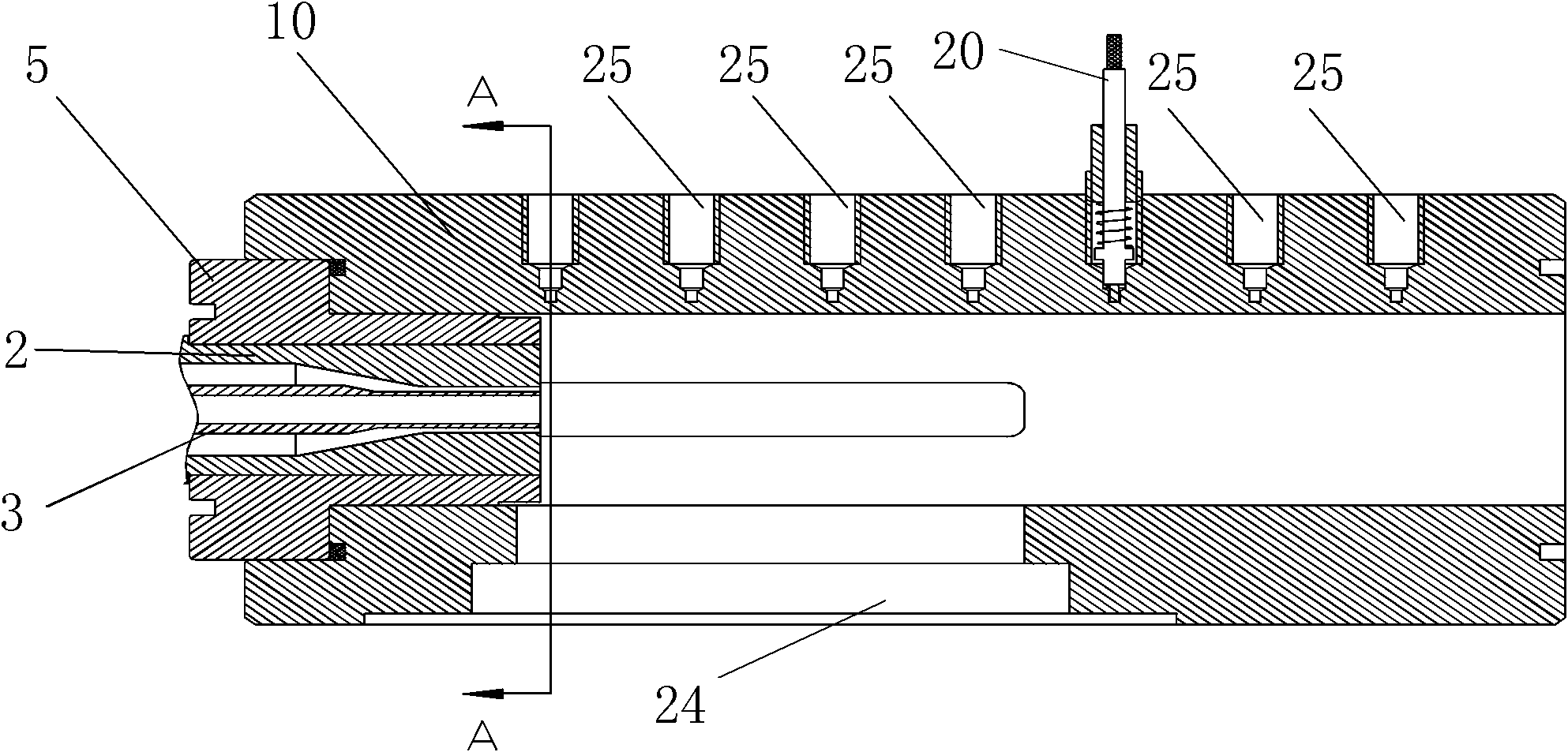
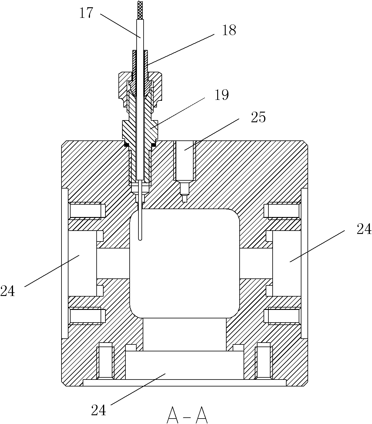
[0035] The invention is a transparent combustion chamber with a square inner channel, which is divided into a head mechanism, a body mechanism of the combustion chamber, an observation window mechanism and a guide mechanism.

[0036] The head mechanism includes an oxidant chamber 1, a fuel nozzle 2, an oxygen nozzle 3 and a fuel chamber 4, such as figure 1 As shown, the outlets of the oxygen nozzle 3 and the fuel nozzle 2 are both circular cross-sections, which are convenient for processing. The two are sealed with an O-ring, and the gap between the oxygen nozzle 3 and the fuel nozzle 2 is fitted. To ensure coaxiality, there is a fuel channel between the oxygen nozzle 3 and the fuel nozzle 2, the fuel enters through the fuel channel, and enters the transparent combustion chamber along the fuel nozzle 2, and the oxygen nozzle 3 is attached to the surfa...


PUM


Abstract

The invention discloses a transparent combustion chamber with a square interior passage, belonging to the field of the design of transparent combustion chambers for liquid-propellant rocket engines. The transparent combustion chamber comprises a head mechanism, a combustion chamber body mechanism, an observation window mechanism and a guiding mechanism; wherein the head mechanism comprises an oxidant cavity, a fuel nozzle, an oxygen nozzle and a fuel cavity; the combustion chamber body mechanism comprises a combustion chamber body substrate and a pressure-measuring filler neck; the observation window mechanism comprises an observation window cover plate and quartz glass; and the guiding mechanism comprises an head guiding slot and a tail guiding flange. In the invention, the observation window cover plate, the quartz glass and the combustion chamber substrate are mutually sealed with square graphite which expands to fill gaps among the observation window cover plate, the quartz glass and the combustion chamber substrate, so that glass can be ensured to be contactless with metal so as to play the role of protecting the quartz glass. The design of the square interior channel of the combustion chamber is favorable for leveling a quartz glass sheet to the inner wall surface of the combustion chamber and reducing the disturbance to an inner flow field of the combustion chamber; and four corners of the square interior channel are transitioned by adopting large circular arcs so as to prevent stress concentration.

Description

technical field [0001] The invention relates to a transparent combustion chamber with a square inner channel, which belongs to the field of transparent combustion chamber design for liquid rocket engines. Background technique [0002] Injectors are key components of liquid rocket engines. Before the injector is applied, a large number of cold flow and hot tests are required to check whether the performance of the injector meets the requirements. The traditional combustion chamber design limits people’s observation and measurement of the injector’s cold flow and hot test flow fields inside the engine, and it is impossible to directly obtain the structural characteristics of the flow field inside the combustion chamber. The degree of cognition of the hot test mechanism, domestic and foreign research results show that the structural parameters of the injector have an important impact on the performance of the injector, and the flow field at the outlet of the injector affects t...

Claims


Application Information

Patent Timeline
Patent Type & Authority Applications(China)
IPC IPC(8): F02K9/62F02K9/96
Inventor 蔡国飙陈泽高玉闪金平
Owner BEIHANG UNIV
Why Eureka
Try Eureka