Fume Hood Sensor Bonding Fixture

A technology of sensors and smoke hoods, which is applied to home appliances, oil fume removal, and household stoves/stoves. It can solve problems such as product quality degradation, low work efficiency, and deformation of the raised part 12a, and achieve product quality assurance and labor intensity reduction. , The effect of improving the bonding efficiency

Active Publication Date: 2020-06-02
NINGBO FOTILE KITCHEN WARE CO LTD
View PDF4 Cites 0 Cited by
  • Summary
  • Abstract
  • Description
  • Claims
  • Application Information

AI Technical Summary

Problems solved by technology

[0002] figure 1 and figure 2 It is an outer frame 1a of a smoke collecting hood of a range hood in the prior art. The bulge 12a on the back forms a guide area for the oil fume. The bulge 12a only gradually rises inward around the periphery, and has upwardly bent flanges on both sides. 11a, the outer end of the flange part also has an L-shaped bending part 13a, and there is a narrow area between the flange part 11a and the raised part 12a. During the production of the smoke hood, the sensor 2a needs to pass through the narrow area and then be installed on the flange On the inner side of the flange part 11a, and the L-shaped bending part 13a will cover the mounting plate 21a of a part of the sensor, if the sensor is arranged on the inner side of the flange part by manual operation, there will be the following problems: First, due to the narrow The area is relatively small, and it is difficult for workers to place their fingers, resulting in inflexible operation and inaccurate installation. Second, bumps and collisions between the sensor and the raised part 12a are inevitable during the operation process, causing the raised part 12a to deform or the sensor to fail , product quality declines; third, higher operating requirements for workers, fourth, lower work efficiency

Method used


Image

  • Fume Hood Sensor Bonding Fixture
  • Fume Hood Sensor Bonding Fixture
  • Fume Hood Sensor Bonding Fixture

Examples


Embodiment Construction

[0025] The present invention will be further described in detail below in conjunction with the accompanying drawings and embodiments.

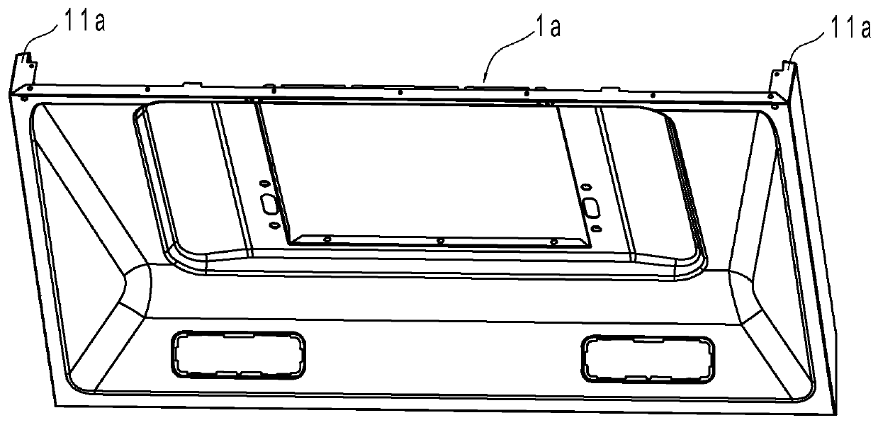
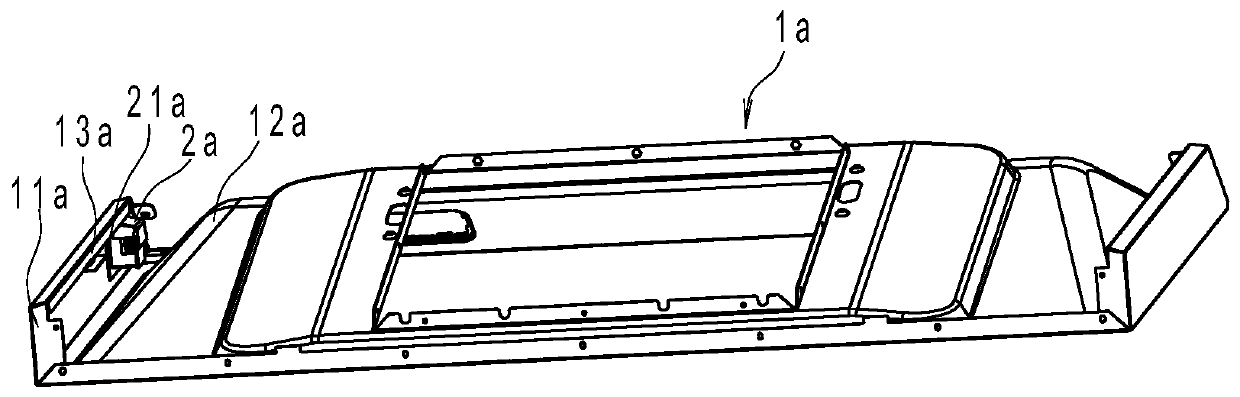
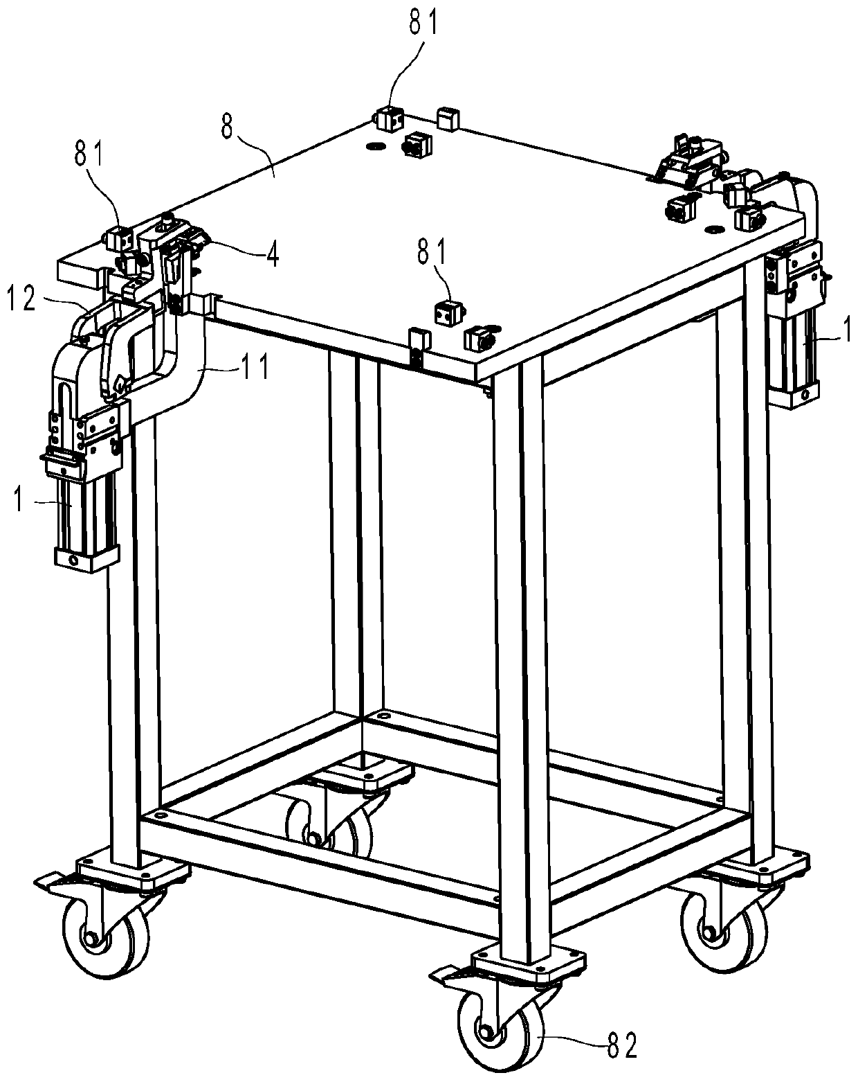
[0026] like image 3 , Figure 4 and Figure 5 As shown, the fume collecting hood sensor bonding fixture in this embodiment includes a workbench 8, a driving cylinder 1, a support 3, a suction cup 4, a reset member 51, a guide block 7 and a pull rod 6, and the upper end surface of the workbench 8 is provided with a The positioning block 81 of the outer frame 1a of the smoke collecting hood is positioned; the bottom end of the workbench 8 is provided with a pulley 82, which is convenient for moving.

[0027] A workbench 8 in this embodiment has two sets of driving cylinders 1, and correspondingly, there are two sets of positioning blocks 81 with the same structure, and the following description is made for one set.

[0028] The driving cylinder 1 is located on one side of the workbench 8. The driving cylinder 1 in this embodiment is the JCK ...


PUM


Abstract

The invention discloses a bonding clamping tool for smoke collecting cover sensors. The clamping tool is characterized in that the clamping tool includes a workbench (8), driving air cylinders (1), supporting brackets (3), suckers (4), reset pieces (51), guide blocks (7) and pull rods (6); the suckers (4) are arranged on the front ends of the supporting brackets (3) and have external air source access ports, and the lower end faces of the suckers (4) have accommodating areas fitting with the shapes of sensors; each guide block (7) is arranged on one side of the workbench (8) and close to the corresponding sucker (4), the upper end openings of the guide blocks (7) form U-shaped port grooves (71), and the outer side faces on the lower ends of the guide blocks have flat guide surfaces (72); the pull rods (6) include rod parts, interconnecting pieces (63) on the front ends of the rod parts and cam parts (61) on the rear ends of the rod parts; the interconnecting pieces (63) are located inthe port grooves (71) of the guide blocks (7) and connected to the suckers (4); and the cam parts (61) can cooperate with the guide surfaces (72) of the guide blocks (7) so that the suckers (4) can move horizontally. Thus, bonding efficiency can be greatly enhanced, product quality can be well guaranteed, and labor intensity can be reduced.

Description

technical field [0001] The invention relates to a bonding tool for a sensor on a smoke collecting hood. Background technique [0002] figure 1 and figure 2 It is an outer frame 1a of a smoke collecting hood of a range hood in the prior art. The bulge 12a on the back forms a guide area for the oil fume. The bulge 12a only gradually rises inward around the periphery, and has upwardly bent flanges on both sides. 11a, the outer end of the flange part also has an L-shaped bending part 13a, and there is a narrow area between the flange part 11a and the raised part 12a. During the production of the smoke hood, the sensor 2a needs to pass through the narrow area and then be installed on the flange On the inner side of the flange part 11a, and the L-shaped bending part 13a will cover the mounting plate 21a of a part of the sensor, if the sensor is arranged on the inner side of the flange part by manual operation, there will be the following problems: First, due to the narrow The ...

Claims


Application Information

Patent Timeline
Patent Type & Authority Patents(China)
IPC IPC(8): F24C15/20
CPCF24C15/2021
Inventor 叶群郑飞茅忠群诸永定李立波
Owner NINGBO FOTILE KITCHEN WARE CO LTD
Why Eureka
Try Eureka