Heat exchanger

a technology of heat exchanger and core plate, which is applied in the direction of lighting and heating apparatus, stationary conduit assemblies, reinforcement means, etc., can solve the problems of reduced formability of ribs and burring parts, high stress may be generated over the tubes in the tube width direction, etc., and achieve the effect of improving the formability of the core pla

Active Publication Date: 2008-01-03
DENSO CORP
View PDF12 Cites 32 Cited by
  • Summary
  • Abstract
  • Description
  • Claims
  • Application Information

AI Technical Summary

Benefits of technology

[0011]In view of the foregoing problems, it is an object of the present invention to provide a heat exchanger which can restrict a stress concentration at ends portions of tube in a tube width direction (tube major direction) while a formability of a core plate is improved.
[0013]When a temperature of one of the tube is different from that of an adjacent tube, the ribs restrict a deformation of the portions of the tube holes, thereby a stress concentration at the end portions of the tubes in the third direction is restricted. In addition, a thermal strain of the tube is absorbed by a deformation of the deformable part. Furthermore, the length of the ribs in the third direction is short, thereby a formability of the ribs is improved.
[0017]In this case, a stress generated in the vicinity of end portions of the tube holes in a tube width direction (corresponding to a third direction approximately perpendicular to the first and second directions) are dispersed to the ribs, thereby the ribs restrict a deformation of the end portions of the tube holes due to a difference in temperature of the tubes. Therefore, a stress concentration at the end portions of the tubes in the tube width direction is restricted. In addition, a length of the ribs in the tube width direction becomes short, thereby a formability of the ribs is improved.
[0019]A rigidity of surrounding areas of the tube holes in the tube insertion plate part is increased by the burring parts. Thus, when a strain is generated in the tubes, the burring parts restrict a deformation of the end portions of the tube holes in a tube width direction, thereby a stress concentration at end portions of the tubes in a tube width direction is restricted.
[0021]In general, a thickness of the insert is larger than that of the tubes, thereby the insert is hardly damaged by a stress concentration. Therefore, when the burring parts are arranged only at the inner peripheral edges of a part of the tube holes, a stress concentration at end portions of the tubes in the tube width direction is restricted while a formability of the core plate is improved.

Problems solved by technology

However, when the core plate has the ribs, the core plate is difficult to be deformed in the longitudinal direction of the tubes, thereby a high stress may be generated over the tubes in the tube width direction.
However, as the protruding dimensions of the ribs and burring parts are large, the formability of the ribs and the burring parts are reduced.

Method used


Image

  • Heat exchanger
  • Heat exchanger
  • Heat exchanger

Examples


first embodiment

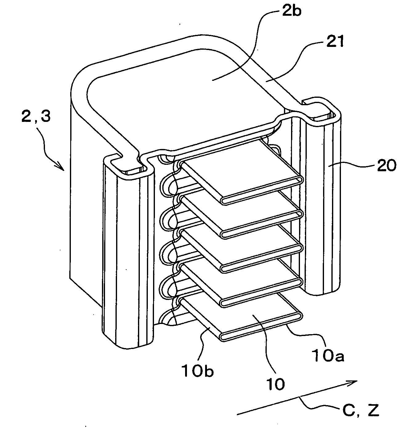
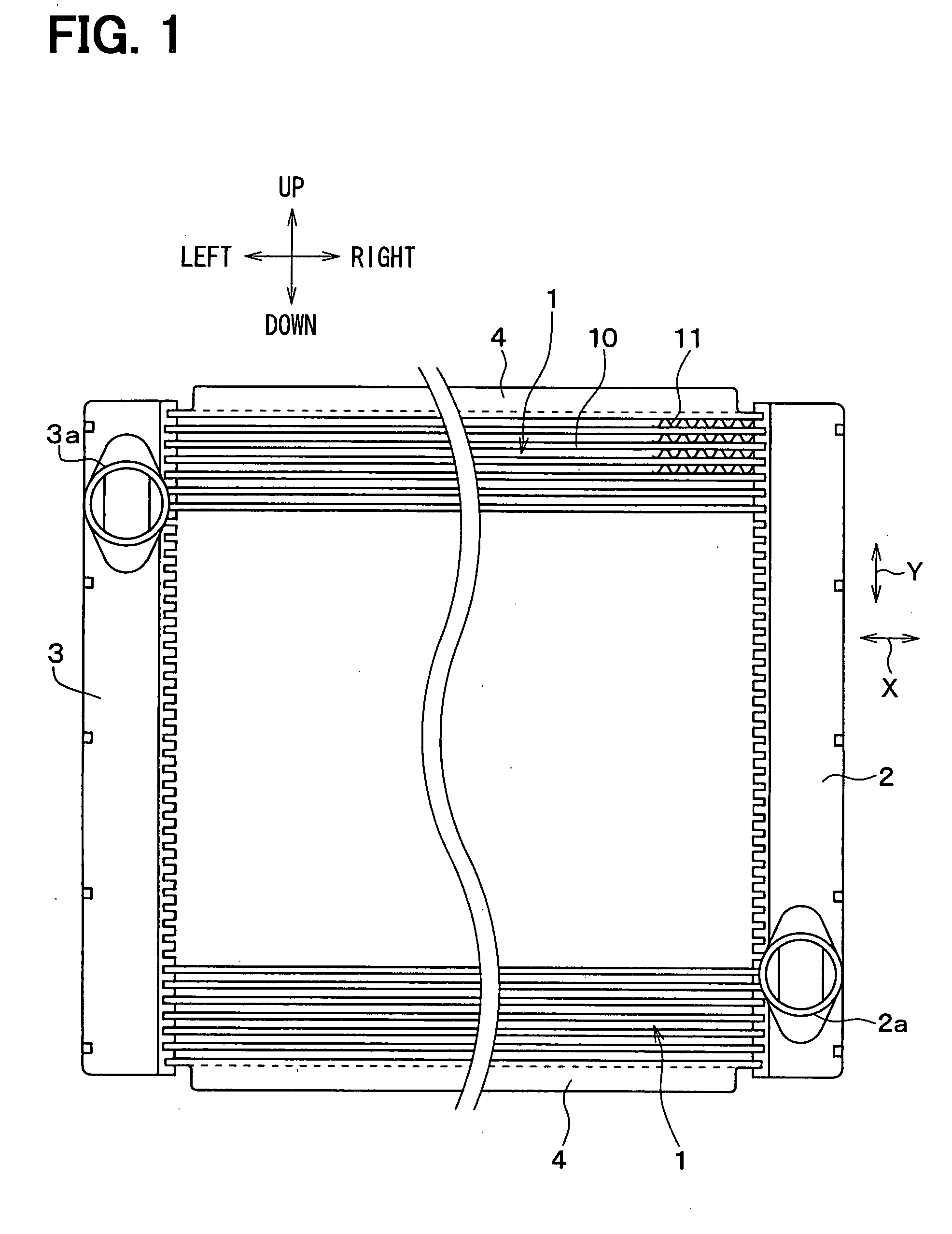
[0043]A heat exchanger according to a first embodiment of the invention can be used for a radiator, for example, for cooling a water-cooled internal combustion engine. As shown in FIG. 1, the heat exchanger includes a core part 1 having an approximately rectangular solid shape. The core part 1 includes a plurality of tubes 10 and a plurality of corrugate fins 11 which are alternately stacked in an up-down direction (tube stacking direction Y) in FIG. 1.

[0044]The corrugate fins 11 have corrugate shapes, and are made of an aluminum alloy, for example. The corrugate fins 11 are arranged for accelerating a heat exchange between air and cooling water (coolant). The tubes 10 define therein water passages through which cooling water for the water-cooled internal combustion engine (not shown) flows. For example, the tubes 10 are made of aluminum alloy plates, which are bent into predetermined shapes and weld or brazed, for example.

[0045]In the heat exchanger in FIG. 1, a longitudinal direct...

second embodiment

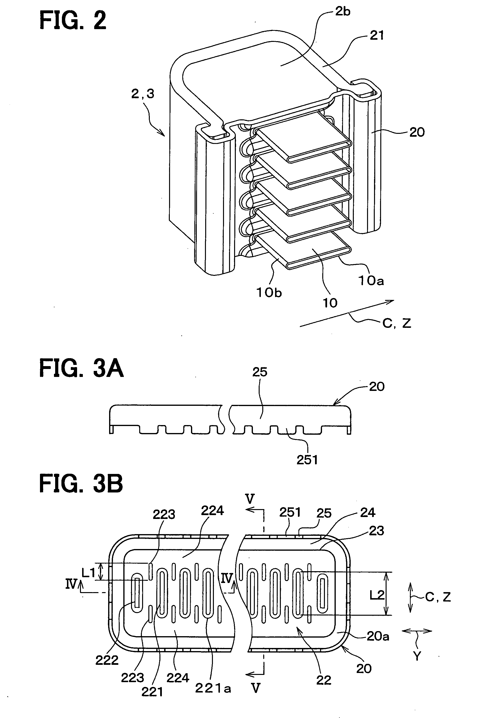
[0064]In the core plate 20 of FIG. 3B, each of the intermediate portions between the tube holes 221 and the insert holes 222 in the tube stacking direction Y is provided with the pair of the ribs 223. Alternatively, a part of the intermediate portions may be provided with the pair of the ribs 223. For example, first intermediate portions each of which is provided with the pair of the ribs 223 and second intermediate portions without any ribs 223 may be alternately arranged in the tube stacking direction Y, as shown in FIG. 6. In other words, the pair of the ribs 223 may be arranged alternately in the intermediate portions in the tube stacking direction Y.

[0065]Alternatively, one of the first intermediate portions provided with the pair of the ribs 223 and two of the second intermediate portions without any ribs 223 may be alternately arranged in the tube stacking direction Y. In other words, the pair of the ribs 223 may be arranged at one of every three adjacent intermediate portion...

third embodiment

[0066]In the core plate 20 of FIG. 3B, each of the intermediate portions between the tube holes 221 and the insert holes 222 in the tube stacking direction Y is provided with the pair of the ribs 223. Alternatively, each of the intermediate portions may be provided with one rib 223 at one end side of the tube holes 221 in the tube major direction Z. For example, one of third intermediate portions having one rib 223 on a first end side of the tube holes 221, and one of fourth intermediate portions having one rib 223 on a second end side of the tube holes 221 may be alternatively arranged, as shown in FIG. 7. Here, the first end side of the tube holes 221 is opposite to the second end side of the tube holes 221 in the tube major direction Z. Also in this case, the number of the ribs 223 is reduced, thereby the formability of the ribs 223 is improved compared with the case where the pair of the ribs 223 is arranged at each of intermediate portions.


PUM


Abstract

A heat exchanger includes tubes and a tank. The tubes extend in a first direction, and are stacked in a second direction. The tank has a tube insertion plate part, and is arranged at an end portion of the tubes. The tube insertion plate part has tube holes in which the tubes are inserted, and ribs extending in a third direction that is approximately perpendicular to the first direction and the second direction. The tube hole has end portions in the third direction. The rib are arranged to overlap with the end portion of the tube hole in the second direction, and to provide a deformable part to be deformable in the first direction. The deformable part is located in the tube insertion plate part outside of the ribs in the third direction.

Description

CROSS REFERENCE TO RELATED APPLICATIONS[0001]This application is based on Japanese Patent Applications No. 2006-179046 filed on Jun. 29, 2006 and No. 2006-298690 filed on Nov. 2, 2006, the contents of which are incorporated herein by reference in its entirety.BACKGROUND OF THE INVENTION[0002]1. Field of the Invention[0003]The present invention relates to a heat exchanger which can be used for a radiator, for example.[0004]2. Description of the Related Art[0005]Conventionally, a heat exchanger includes a plurality of tubes and a plurality of corrugate fins, which are alternately stacked to form a core part. The heat exchanger further includes tanks arranged at longitudinal ends of the tubes. Each of the tanks includes a core plate having tube holes in which the tubes are inserted, and a tank body fixed to the core plate to provide a space in the tank with the core plate. The core plate has a first wall part (tube insertion plate part) having the tube holes. At an outer peripheral por...

Claims


Application Information

Patent Timeline
Patent Type & Authority Applications(United States)
IPC IPC(8): F28F9/02
CPCF28D1/05366F28F2225/08F28F9/0226F28D2021/0094
Inventor SUGITO, HAJIMEOSAKABE, HIROYUKIHIROSE, HIROKAZUUNO, TAKAHIRO
Owner DENSO CORP
Why Eureka
Try Eureka