Battery array, battery separator, and vehicle equipped with battery array

a battery array and battery separator technology, applied in the direction of batteries/cells, cell components, propulsion by batteries/cells, etc., can solve the problems of battery cell damage, deformation or damage of battery cells, so as to achieve accurate disposed of, and accurate battery cell temperature detection

Inactive Publication Date: 2013-10-03
SANYO ELECTRIC CO LTD
View PDF5 Cites 33 Cited by
  • Summary
  • Abstract
  • Description
  • Claims
  • Application Information

AI Technical Summary

Benefits of technology

[0009]In the battery array described above, each battery cell is disposed between the partition plates of adjacent separators and a plurality of battery cells and separators are stacked together. When the stack of battery cells and separators is sandwiched between endplates, stress concentration at the upper ends of the battery cells can be prevented. This is because when the separator partition plates are sandwiched between battery cells and pressure is applied by the endplates, thin regions established on the partition plates prevent excessive pressure application on the battery cell surfaces and alleviate stress concentration at the upper ends of the battery cells. This can prevent deformation and damage at the edges of the upper ends of the battery cells.
[0022]The battery separator for the twelfth aspect of the present invention can be provided with thin regions established opposite the perimeters of the battery cells, and those thin regions are formed thinner than the region opposite the center sections of the battery cells. When this battery separator is inserted between battery cells, a plurality of battery cells and separators are stacked together, and the stack is sandwiched between endplates at the ends of the stack, stress concentration at the battery cell perimeters can be prevented. This is because application of strong pressure forces to battery cell perimeters is prevented by the thin regions established in separator regions opposite the battery cell perimeters, and this can prevent stress concentration at the battery cell perimeters. As a result, this battery separator has the positive feature that when battery cells and separators are pressed together by the endplates, deformation or damage to the outer edges of the battery cells can be avoided. In particular, the center section of a battery cell is in external case planar regions that can deform flexibly with relative ease, and that section is not immediately damaged even if pressure forces are applied. This achieves the positive feature that the stack of battery cells can be reliably held together while protecting battery cell perimeter regions.

Problems solved by technology

This has the detrimental effect that the battery cell can become deformed or damaged.
As a result, extremely high, locally applied stress develops and becomes a cause of battery cell damage.

Method used


Image

  • Battery array, battery separator, and vehicle equipped with battery array
  • Battery array, battery separator, and vehicle equipped with battery array
  • Battery array, battery separator, and vehicle equipped with battery array

Examples


Embodiment Construction

)

[0037]The following describes embodiments of the present invention based on the figures. However, the following embodiments are merely specific examples of a battery array, battery separator, and vehicle equipped with the battery array representative of the technology associated with the present invention, and the battery array, battery separator, and vehicle equipped with the battery array of the present invention is not limited to the embodiments described below. Further, components cited in the claims are in no way limited to the components indicated in the embodiments.

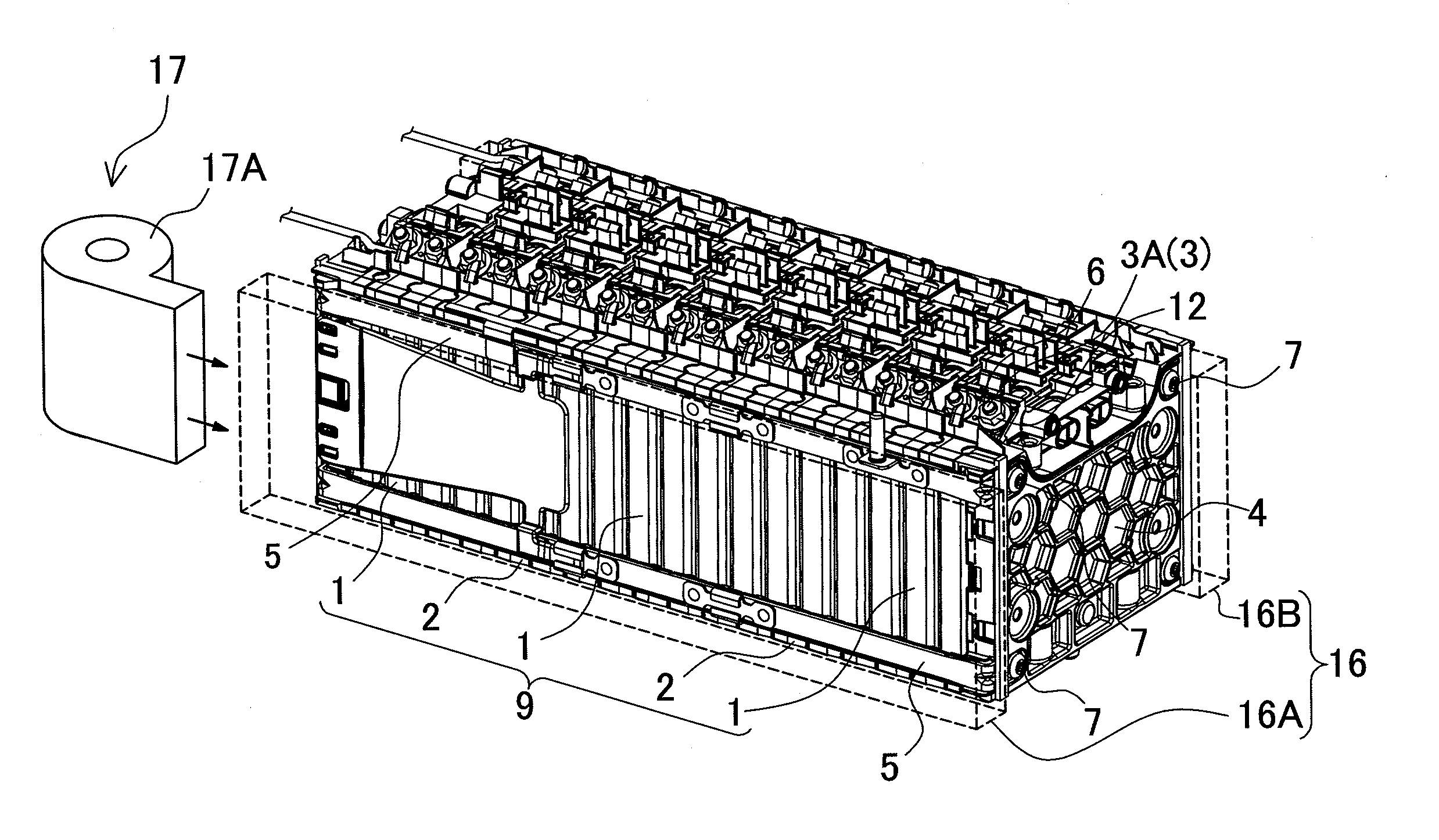
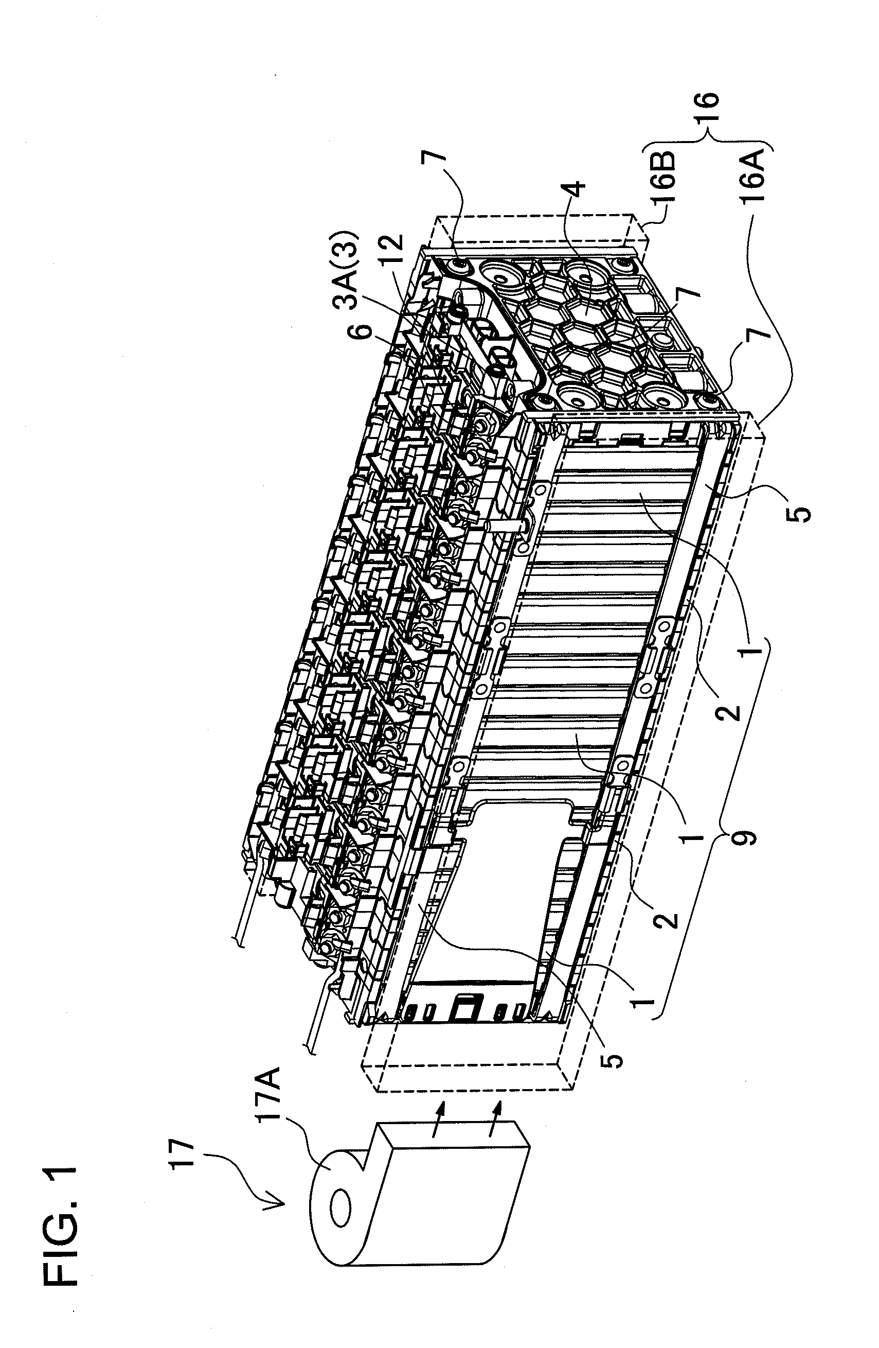
[0038]The battery array shown in FIG. 1 is optimally suited for a power source primarily in an electric powered vehicle such as a hybrid vehicle (hybrid car, hybrid electric vehicle, HEV) driven by both an electric motor and an engine or an electric vehicle (EV, electric automobile) driven by an electric motor only. However, the battery array can also be used in applications other than electric powered vehicle app...


PUM

PropertyMeasurementUnit
widthaaaaaaaaaa
widthaaaaaaaaaa
thicknessaaaaaaaaaa

Abstract

The battery array is provided with a plurality of battery cells having a rectangular outline, insulating separators intervening between adjacent battery cells, a pair of endplates disposed at the ends of the battery cells stacked alternately with intervening separators, and binding bars that bind the endplates together. Partition plates, which are the parts of the separators sandwiched between adjacent battery cells, have thin regions established along regions opposite the upper ends of the battery cells, and the thin regions are formed thinner than partition plate regions opposite the center sections of the battery cells.

Description

BACKGROUND OF THE INVENTION[0001]1. Field of the Invention[0002]The present invention relates to a battery array and battery separator used primarily in apparatus such as a power source that powers a motor to drive a vehicle such as a hybrid vehicle or electric vehicle, and to the vehicle equipped with the battery array[0003]2. Description of the Related Art[0004]A vehicle (automobile) such as an electric vehicle (EV, electric automobile) driven by an electric motor, or a hybrid vehicle (hybrid car, hybrid electric vehicle, HEV) driven by both an electric motor and an engine carries on-board a power source apparatus, which has battery cells housed in an external casing. To achieve an output capable of driving the vehicle with the motor, the power source apparatus has many battery cells connected in series to increase the output voltage. For example, battery cells with rectangular external cases are stacked to form a battery array, and a power source apparatus is configured by connec...

Claims


Application Information

Patent Timeline
Patent Type & Authority Applications(United States)
IPC IPC(8): H01M2/10B60L50/64
CPCH01M2/1077H01M10/0481H01M10/5016H01M2/1083H01M10/5059H01M2220/20H01M10/5032H01M10/625H01M10/647H01M10/6557Y02E60/10H01M50/249B60L50/64H01M50/209H01M50/224Y02T10/70
Inventor OKADA, WATARUNAKAMURA, SHINSUKEUEMURA, KENTAROWAKABAYASHI, AKINOBU
Owner SANYO ELECTRIC CO LTD
Why Eureka
Try Eureka