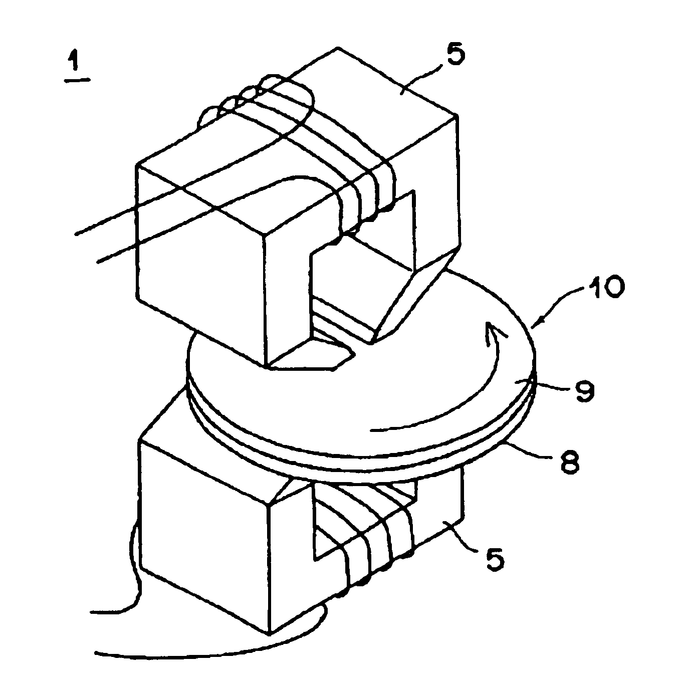
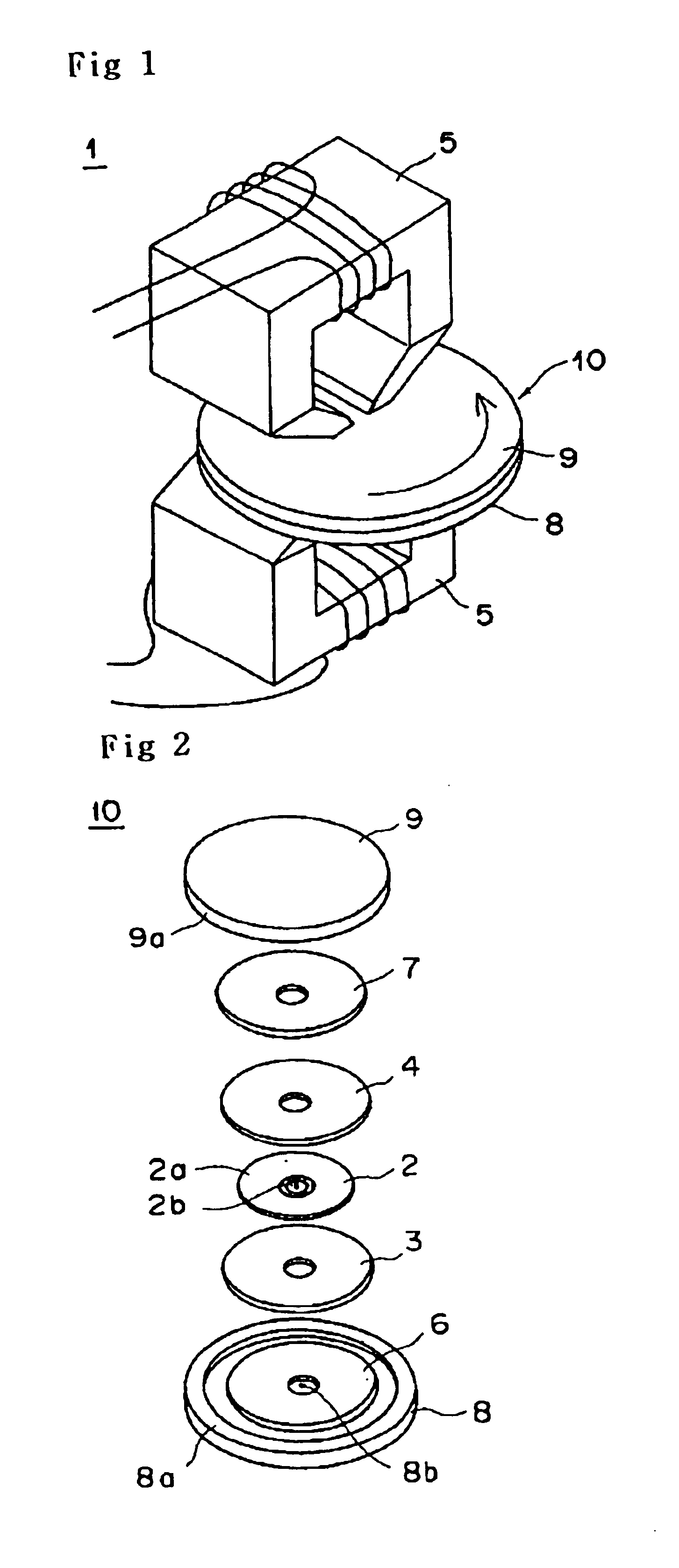
[0026]According to another aspect of the present invention, there is provided a magnetic transfer apparatus which executes magnetic transfer by applying
magnetic field for transfer after a master carrier that bore information signals and a slave medium to be subjected to magnetic transfer are brought into confronted close contact and received within a holder, characterized in that an elastic member is interposed between the holder and the master carrier and preferably the quantity of dusts having a size of 0.5 μm or over is not more than 0 particles / cm2 and the quantity of dusts having a size of not less than 0.3 μm and less then 0.5 μm is not more than 5 particles / cm2, generated from the surface of said elastic member. In this case, said elastic member was formed from a material having a low dustability or treated with cleaning process for removing dusts so as to establish the quantity of dusts with a size of 0.5 μm or over is not more than 0 particles / cm2 and the quantity of dusts with a size of not less than 0.3 μm and less then 0.5 μm is not more than 5 particles / cm2, even when it undergoes repeated close contact and release with respect to the slave medium. Also, a particle smaller than 0.3 μm will be difficult to cause signal omission in view of the size and the like of pattern according to information to be transferred.
[0035]In addition, if a close
contact force between a master carrier and a slave medium received within a holder is made to be obtained by vacuum suction of
closed space of holder, it is possible to apply an uniform pressure, and by setting the
area ratio (SV / SD) of an effective area (SV) of vacuum suction region of holder and a contact area between the master carrier and slave medium in the range of 1.2˜16.0, the slave medium and master carrier are brought into uniform close contact with each other with a predetermined
contact pressure, whereby it is possible to execute good magnetic transfer with a high transfer
signal quality. If said
area ratio (SV / SD) is increased to enlarge the area of
closed space of holder as compared to the contact area of slave medium, the pressure acting on a portion which does not retain master carrier is applied for the close contact of master carrier and slave medium, thereby increasing the force for close contact. By setting the
area ratio to be not less than 1.2, it is possible to obtain required close contact in uniform, whereby the close contact capability can be enhanced and to secure good transfer
signal quality without local signal omission, and by setting the area ratio to be not more than 16, the applied pressure is not to be excessive, whereby it is possible to prevent deformation and damage of pattern from being caused in the master carrier, thereby enhancing the endurance.
[0036]If the holder takes a construction of cylinder, the pressure produced by vacuum suction effectively acts on the closely contacted surfaces of master carrier and slave medium and the force for close contact is increased, whereby an uniform close contact state can be obtained. The uniformity of close
contact force is remarkably improved as compared to mechanical application of pressure, whereby local signal omission will not be occurred.
[0037]Also, in the present invention, if an elastic member whose generation quantity of dusts having size of 0.5 μm or over is 0 particles / cm2 and size of not less than 0.3 μm and less than 0.5 μm is at most five particles / cm2 is interposed between a holder and a master carrier when executing magnetic transfer after the master carrier and slave medium are in confronted close contact with each other and received within the holder, deposited material due to generation of dusts from the elastic member is reduced thereby inhibiting poor close contact and largely reducing signal omission, and the elastic member is deformed in the form of deposited material when the force for close contact is applied, thereby reducing gap-formed extent between the master carrier and slave medium around the deposited material, whereby signal omission created extent can be narrowed and the quality transfer signals can be enhanced.
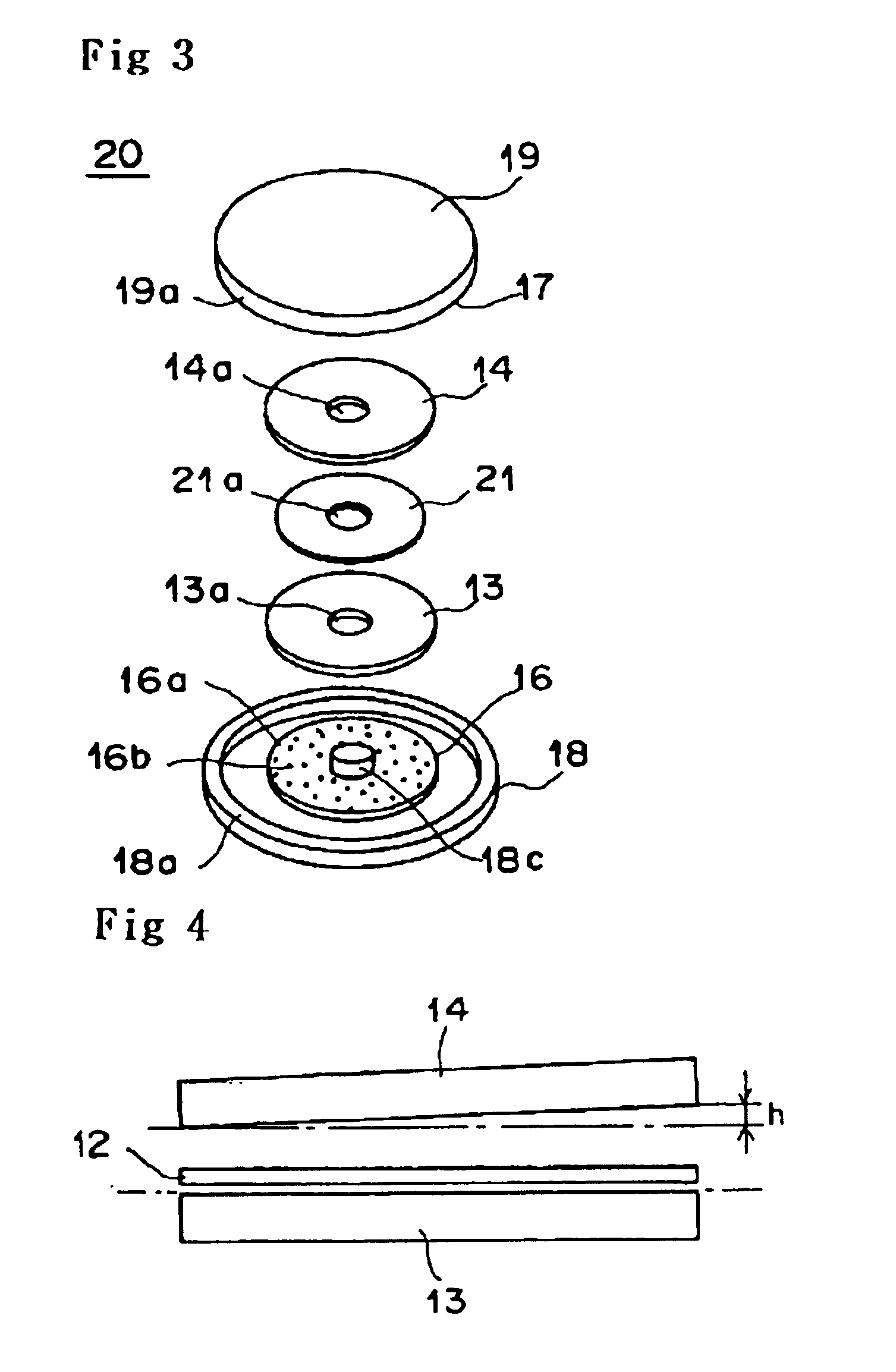
[0038]Still yet, if the magnetic transfer method of the present invention is performed in such a manner that the magnetic field is applied in the state that a master carrier and a slave medium is spaced 1˜100 nm, it is possible to reduce friction produced between the slave medium and unevenness pattern of master carrier, and to effectively prevent the abrasion of unevenness pattern at the time of positioning of slave medium and unevenness pattern, especially because the friction between the slave medium and unevenness pattern which is considered as a major reason of unevenness can be reduced. Also, because the unevenness pattern of master carrier and slave medium are not in close contact with each other, deficiency and
ablation of
magnetic layer can be prevented, which were caused by the repeated close contact and release of master carrier and slave medium. Therefore, the service life of master carrier can be increased and magnetic transfer for more slave mediums will be possible. By this, it is possible to reduce the cost of magnetic transfer, whereby preformat-completed slave mediums can be provided in a low price.


