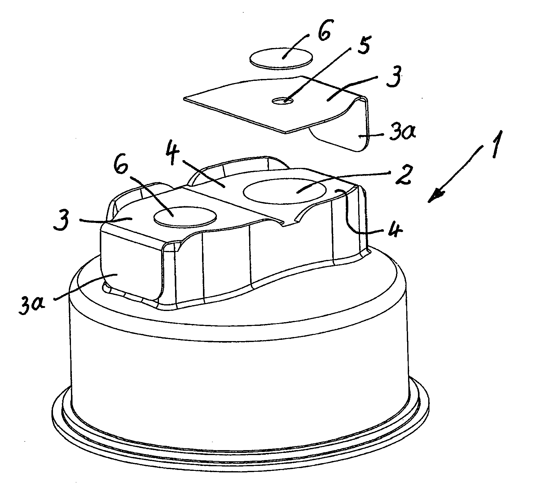
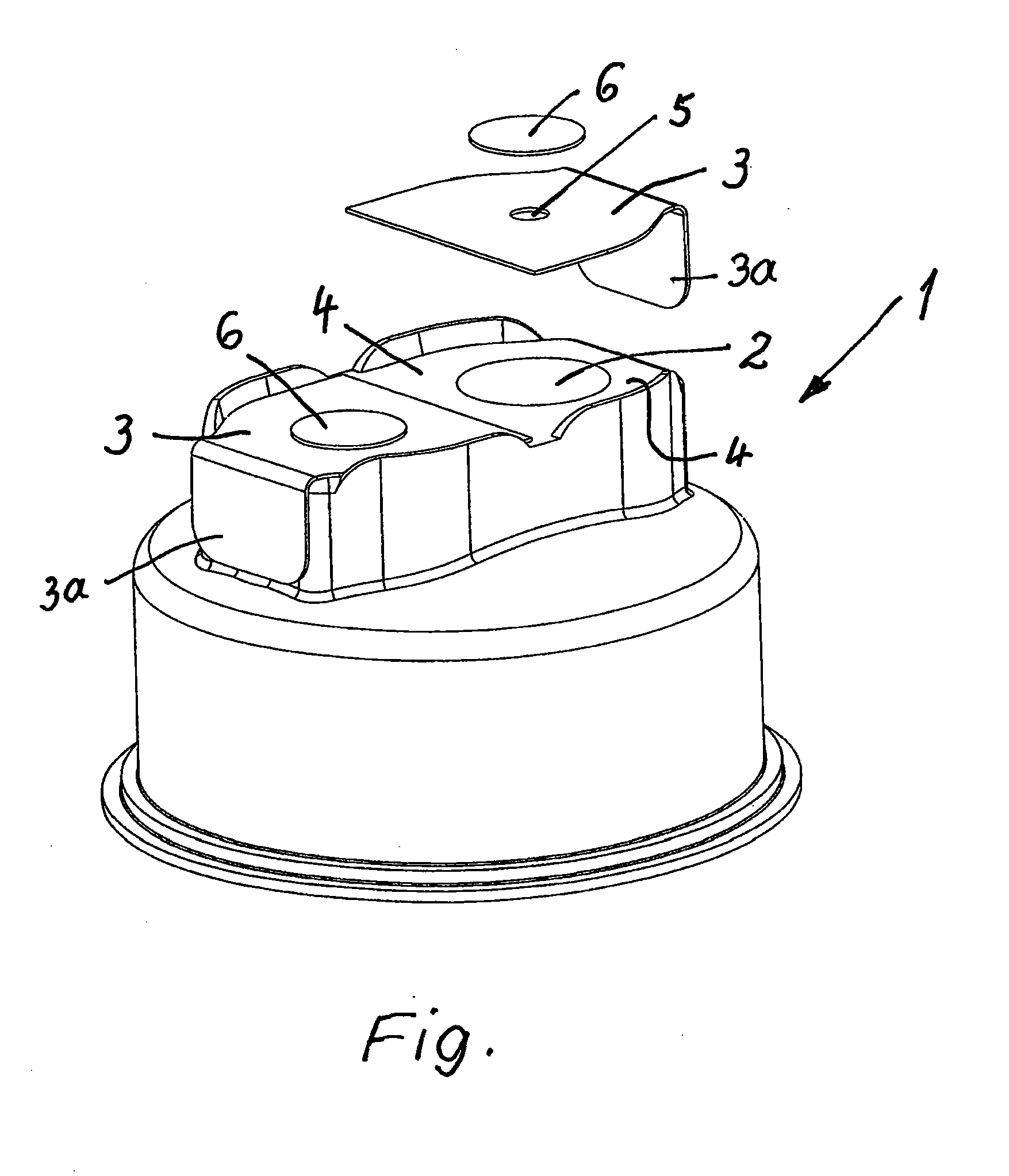
[0019]Here, the sole FIGURE shows, in a perspective diagram, a cap-like, pierceable closure with a cover for the pierceable position, with this cover being able to be detached through peeling, wherein two pierceable positions are provided and the peelable cover reaching across both positions is to be seen in the position of use at one pierceable position and in an exploded-view representation at the other pierceable position.
[0020]A pierceable closure designated as a whole with 1 for medicine containers has approximately the shape of a cap and has two pierceable positions 2 on the top side facing away from the medicine container in the position of use. In the original position, these pierceable positions are covered by a detachable, sterile cover 3 that is formed as a metal or aluminum foil and that is connected, preferably sealed with the closure 1 around the pierceable positions 2 so that it can be ripped or peeled off. Here, this cover 3 covers both pierceable positions 2 and is shown detached on one half in the sole figure for the sake of a better overall view or separated from the other half still located in the position of use.
[0021]Here, the connection region 4 or attachment region, also called “attachment region 4” below, is formed completely surrounding the pierceable position 2, that is, in the embodiment, this attachment position 4 also runs between the two pierceable positions 2, so that each pierceable position 2 can be made accessible by lifting and pulling off the cover 3, without the other pierceable position 2 already being exposed.
[0022]In FIG. 1, one clearly sees that the cover 3 has, within the attachment region 4, a break-out or an opening 5 that is closed in a sterile way with a water vapor-permeable foil or membrane 6. This water vapor-permeable foil 6 can be made of plastic, paper, non-woven fabric, and/or woven fabric and also allows the sterilization of the pierceable region underneath the cover 3, in which, during the autoclaving, hot steam can pass through this membrane 6 and sterilize and then also escape again, so that the advantages of a metal or aluminum foil are combined with a water vapor-permeable foil.
[0023]In the embodiment, the membrane 6 grips over the edge of the opening 5 of the foil 3 on the side facing away from the closure 1, so that the membrane 6 is reliably lifted every time the film 3 is pulled off when its tab 3a is gripped.
[0024]As already mentioned, in the embodiment, the closure 1 has two pierceable positions 2 and a foil cover 3 that covers the two pierceable positions 2, wherein, for each pierceable position 2, a separate foil cover 3 with an opening 5 and membrane 6 or a continuous cover 3 with two openings 5 and two membranes 6 could be provided. The membrane 6 is preferably connected to the cover 3 made of metal, for example, by a hot adhesive. The opening 5 can have a size of at least approximately two square millimeters or also more, for example, of approximately three, four, or five square millimeters or an intermediate value. This size could be selected according to the total size of the cover 3 and the requirement to be able to let the vapor, during the autoclaving, to penetrate as quickly as possible into and under the attached cover 3.
[0025]The pierceable closure 1, for example, a cap for a bottle for infusion solutions, has a peelable, sealable foil as a sterile cover 3 of the pierceable position 2 that is formed as a metal or aluminum foil and is connected or sealed detachably to the closure 1 at a distance around the pierceable position 2. Within the attachment region 4 loaded by the cover, this cover 3 has at least one break-out or opening 5 that is closed in a sterile way with a water vapor-permeable foil or membrane 6, so that the closure 1 can also be sterilized by autoclaving underneath this cover 3.
[0026]Through this arrangement, later contamination of the pierceable position or positions 2 is prevented and a tamper-evident closure is simultaneously formed.
[0027]It will be appreciated by those skilled in the art that changes could be made to the embodiments described above without departing from the broad inventive concept thereof. It is understood, therefore, that this invention is not limited to the particular embodiments disclosed, but it is intended to cover modifications within the spirit and scope of the present invention as defined by the appended claims.