Linear spring magnetic strength electric pump

A linear, strong magnetic technology, applied in the field of machinery, can solve the problems of uneven distribution of springs, unsatisfactory service life, and easy breakage, etc., to achieve uniform compression energy distribution, timely heat dissipation, and good working stability.

Active Publication Date: 2017-07-21
ZHEJIANG QIFENG PUMP IND
View PDF9 Cites 0 Cited by
  • Summary
  • Abstract
  • Description
  • Claims
  • Application Information

AI Technical Summary

Problems solved by technology

[0004] The vibrating canned electric pump mentioned above can increase the head, but in the process of use, the applicant found that the end face of the rubber sleeve facing the electromagnetic motor is easily heated to form a focal surface, and the rubber After a period of use, the sleeve is prone to aging or burning due to heat, and the service life is not ideal. The rubber sleeve is in the shape of an abacus bead, and the overall force is uneven, and the compression energy of the spring cannot be evenly distributed, which affects the axial straight line of the pump shaft. Movement, and the vibration of the spring is relatively large, resulting in high working noise, the spring is repeatedly subjected to force vibration, prone to breakage, and the service life is short

Method used


Image

  • Linear spring magnetic strength electric pump
  • Linear spring magnetic strength electric pump
  • Linear spring magnetic strength electric pump

Examples


Embodiment Construction

[0022] The following are specific embodiments of the present invention and in conjunction with the accompanying drawings, the technical solutions of the present invention are further described, but the present invention is not limited to these embodiments.

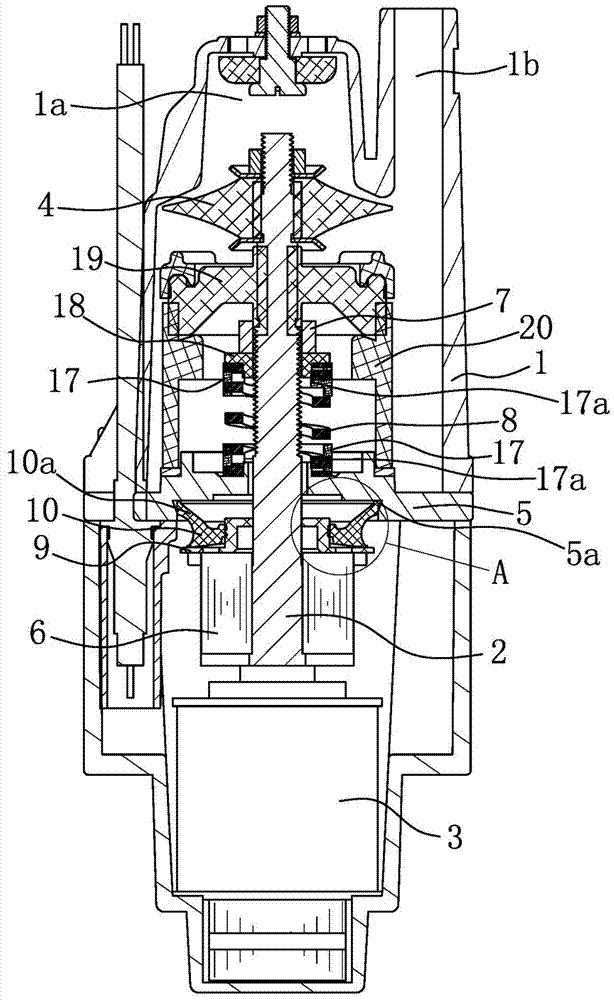
[0023] Such as figure 1 As shown, the linear spring magnetic pump includes a pump body 1, a pump shaft 2 and an electromagnetic motor 3, the electromagnetic motor 3 is fixedly connected to the lower end of the pump body 1, and the top of the pump body 1 is provided with a connected water inlet 1a and the water outlet hole 1b, the pump shaft 2 is located in the pump body 1 and the top of the pump shaft 2 is fixedly connected with the impeller 4 located at the water inlet hole 1a, a rigid bracket 5 is fixedly connected between the pump body 1 and the electromagnetic motor 3, and the pump shaft The lower end of 2 passes through the rigid bracket 5 and is fixedly connected with the iron core 6. The pump shaft 2 is threaded wit...


PUM


Abstract

The invention provides a linear spring magnetic strength electric pump, and belongs to the technical field of machines. The linear spring magnetic strength electric pump solves the problems that an existing linear spring magnetic strength electric pump is short in service life and the like. The linear spring magnetic strength electric pump comprises a pump body, a pump shaft and an electromagnetic motor. A rigid support is fixedly connected between the pump body and the electromagnetic motor. The lower end of the pump shaft penetrates the rigid support and is fixedly connected with an iron core. A thread sleeve is in thread connection to the pump shaft, and the pump shaft is sleeved with a spring. One end of the spring acts on the thread sleeve, and the other end of the spring acts on the rigid support. A sealing structure for preventing water from entering the electromagnetic motor is arranged between an impeller and the rigid support. The pump shaft is sleeved with an auxiliary support located between the rigid support and the iron core. The auxiliary support is sleeved with a rubber auxiliary ring located between the auxiliary support and the rigid support. The auxiliary support is fixed to the iron core. The bottom end of the rubber auxiliary ring is in contact with the auxiliary support. A circle of turned edge is arranged at the top end of the rubber auxiliary ring, and an edge opening of the turned edge is in contact with the rigid support. The linear spring magnetic strength electric pump has the beneficial effects of being stable in work, long in service life and the like.

Description

technical field [0001] The invention belongs to the technical field of machinery, and relates to a pump, in particular to a linear spring magnetic electric pump. Background technique [0002] Building floors in today's society are getting higher and higher, and high-rise water needs to be realized by linear spring magnetic pumps. In the daily use of the traditional linear spring magnetic electric pump, it takes a while to get out of the water at the beginning, and when the water comes out, the pressure will be uneven, and there will be changes in the height of the water column. Therefore, the high-level Residents often encounter problems such as low water flow and intermittent water discharge. In order to increase the water intake and discharge volume of the linear spring magnetic electric pump body, the method of increasing the water inlet hole and the water outlet hole is usually adopted, but the pump body in the prior art is limited by the size of the pump body. This im...

Claims


Application Information

Patent Timeline
Patent Type & Authority Applications(China)
IPC IPC(8): F04D13/06F04D29/66F04D29/08F04D29/58F04D29/042
CPCF04D13/06F04D29/042F04D29/086F04D29/586F04D29/5893F04D29/669
Inventor 江荣华金实斌
Owner ZHEJIANG QIFENG PUMP IND
Why Eureka
Try Eureka