Artificial intervertebral disc

Inactive Publication Date: 2020-03-05
EXPONENTIAL MEDICAL TECH PTY LTD
View PDF0 Cites 0 Cited by
  • Summary
  • Abstract
  • Description
  • Claims
  • Application Information

AI Technical Summary

Benefits of technology

The patent is about a mobile core element that can change from a uncompressed to a compressed configuration. This change in configuration causes the element to become stiffer, which helps the device with which it is used move smoothly. The element is designed to prevent rotational movement when it is compressed. This invention results in a device that can be easily moved and has a spring that stays stiff during use.

Problems solved by technology

Back pain is a common problem that affects many people at some point in their life.
A common cause of back pain is degeneration of the bone surrounding the soft tissue structures of an intervertebral disc, which allow the adjacent vertebrae to move relative to one another.
Another common cause of back pain is the dysfunction of an intervertebral disc, which could be as a result of wear or acute injury, for example.
Damage to an intervertebral disc often results in the destabilization of the spine, which in turn may result in alteration of a natural spacing between adjacent vertebrae.
Such pressure applied to nerves is a known cause of pain and / or nerve damage.

Method used


Image

  • Artificial intervertebral disc
  • Artificial intervertebral disc
  • Artificial intervertebral disc

Examples


first embodiment

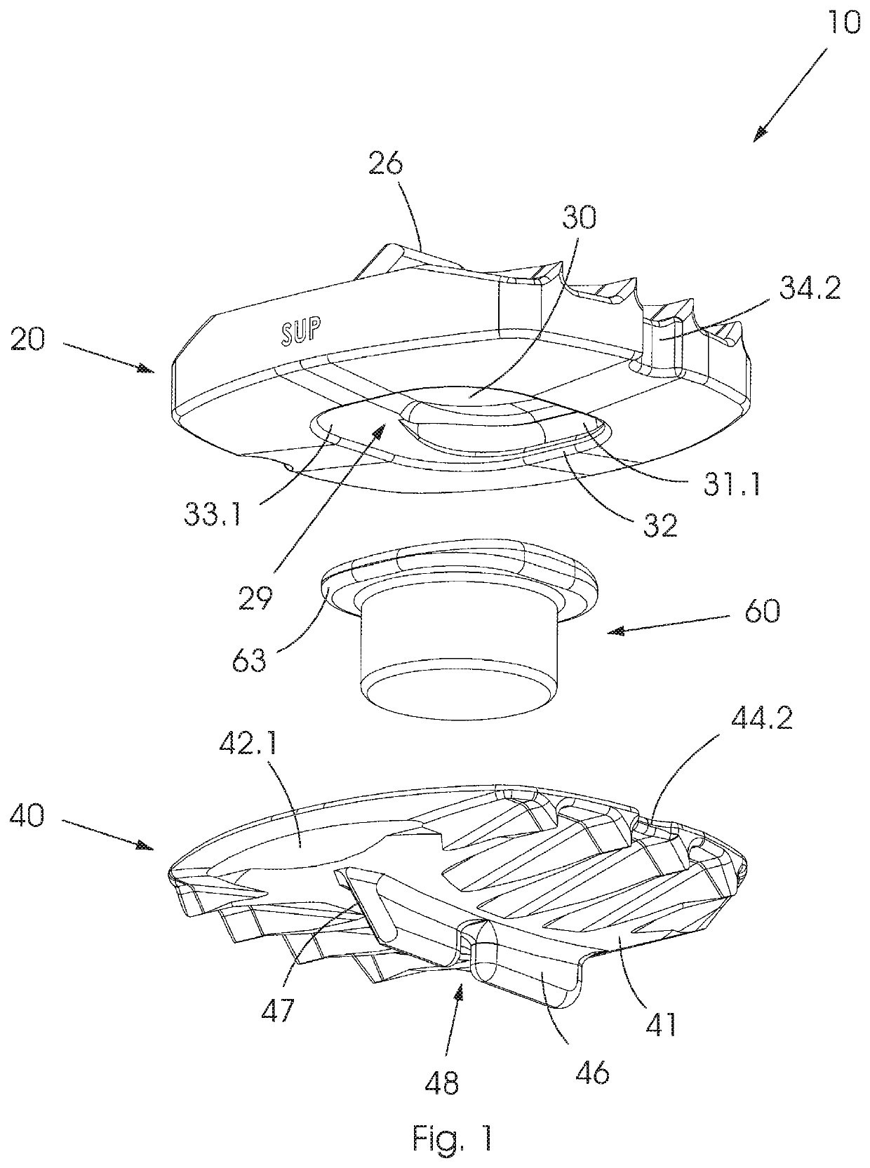
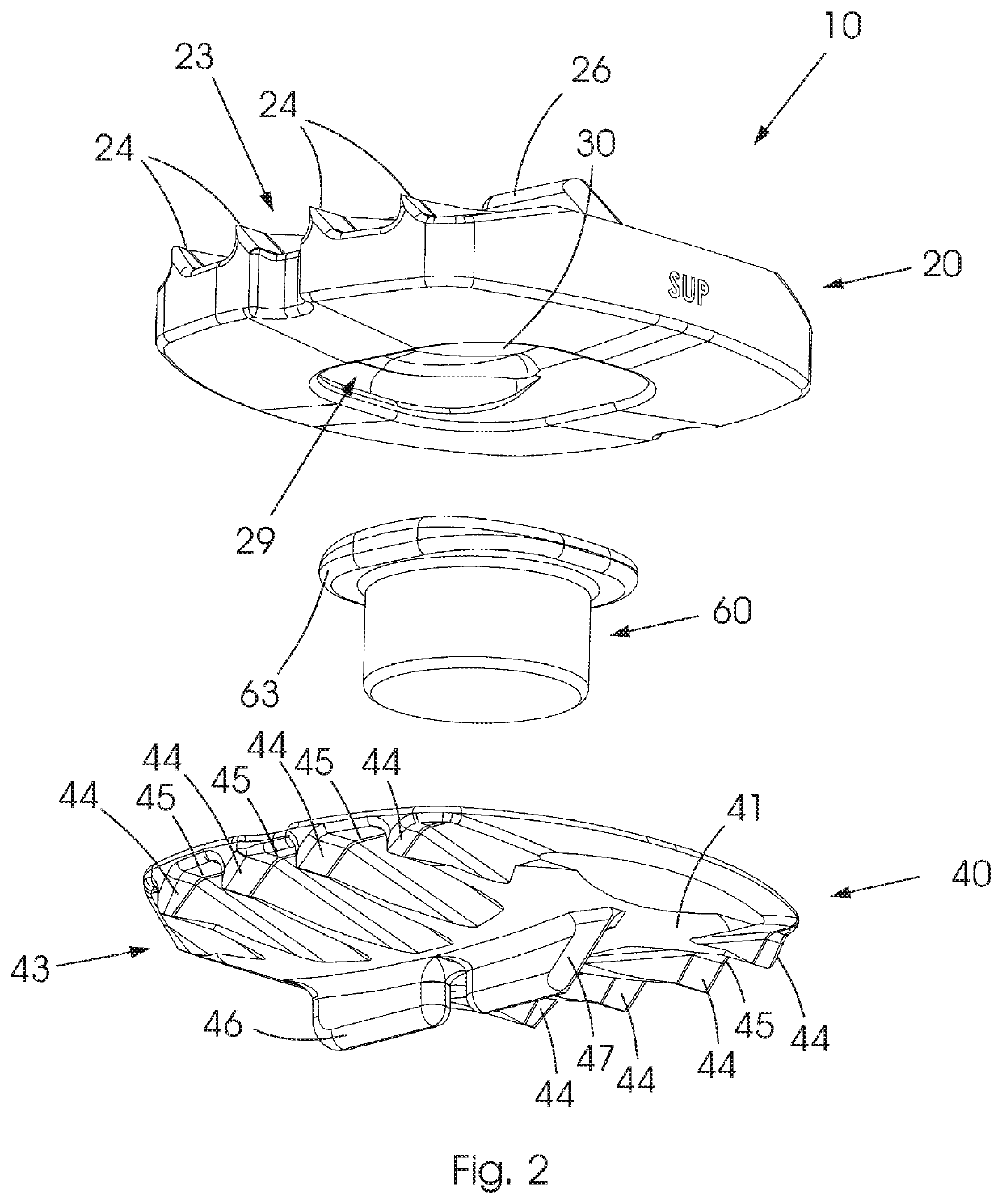
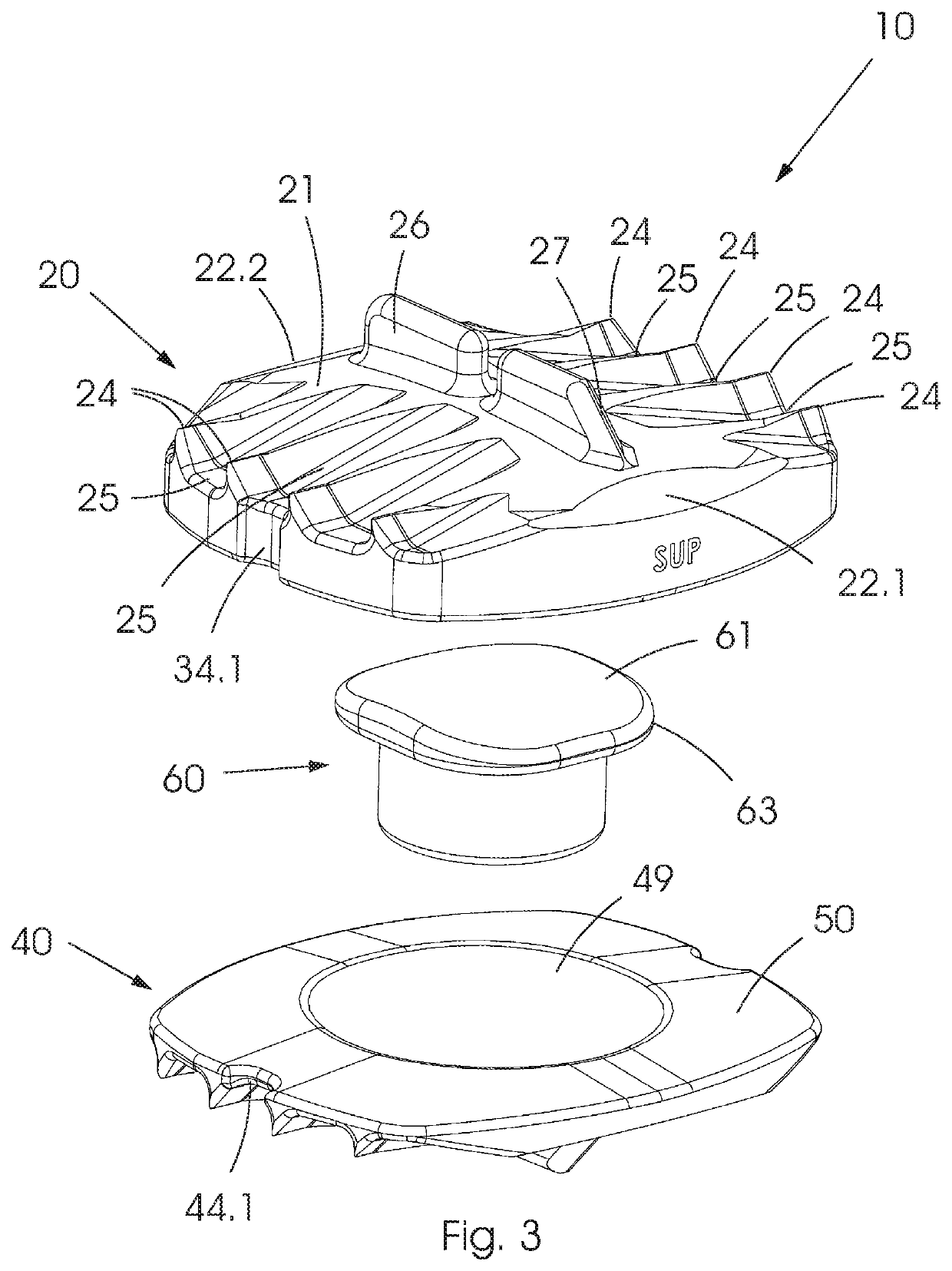
[0110]Referring to the drawings, in which like numerals indicate like features, a non-limiting example of an artificial intervertebral disc in accordance with the invention is generally indicated by reference numeral 10. The artificial intervertebral disc 10 could also be referred to as an intervertebral disc prosthesis.

[0111]FIGS. 1 to 3 show exploded perspective views of the artificial intervertebral disc 10 in accordance with the invention. The intervertebral disc 10 includes a first plate 20, a second plate 40 and a mobile core element 60 in use located between the first and second plates. The first plate 20 and second plate 40 are also referred to as upper and lower plates due to their relative position to each other when a patient who has received the artificial intervertebral disc 10 is in up upright position. In the accompanying drawings the intervertebral disc 10 is shown in exploded view wherein the upper plate 20, lower plate 40 and mobile core element 60 are disengaged f...

second embodiment

[0145]Similarly to the disc 110, the upper body 261 of the mobile core element 260 has a retaining or engaging formation in the form of a continuous peripheral lip 266 carried at an end which is, in use, its upper end. The lip 266 is shaped to engage the complementary shaped engagement formations in the form of the undercut pockets 31.2, 31.2 of the upper plate 20 in order to restrict relative motion between the upper plate 20 and the mobile core element 260 in flexion and extension. In use, the lip 266 further engages the side walls 33.1 and 33.2 of the socket 29 of the upper plate 20 in order to prevent over-translation in lateral bending.

[0146]Referring to FIG. 15, in this second illustrated embodiment of the disc 210 the resilient element 263 is an elliptical, elastic spring component. It should be understood that the word spring does not describe any particular shape of elastic or resilient component. Instead, the word spring is used to describe an elastic device that can be de...


PUM


Abstract

This invention concerns an artificial intervertebral disc for installation in an intervertebral space between adjacent vertebral bodies. The artificial intervertebral disc prosthesis comprises an upper plate, a lower plate and a mobile core element, which is, in use, located between the upper and lower plates. The mobile core element includes a first contoured surface that has a flexion / extension radius that is larger by a determined amount than the radius of its second contoured surface that results in an instantaneous centre of rotation below the midline of the intervertebral disc space, thereby approximating the typical instantaneous centre of rotation of a natural disc. The first contoured surface of the mobile core element has a lateral bending radius that is unequal to the value of the flexion / extension radius, thereby allowing the mobile core element to self-centre on the second surface of the upper plate when under preload. The mobile core element may further be compressible and may include a resilient element located within the mobile core element. Deformation of the resilient element may be contained to obtain an exponential increase in spring stiffness of the resilient element during compression.

Description

BACKGROUND TO THE INVENTION[0001]This invention relates to an artificial intervertebral disc. In particular, but not exclusively, this invention relates to an artificial intervertebral disc comprising a compressible core.[0002]Back pain is a common problem that affects many people at some point in their life. A common cause of back pain is degeneration of the bone surrounding the soft tissue structures of an intervertebral disc, which allow the adjacent vertebrae to move relative to one another. Another common cause of back pain is the dysfunction of an intervertebral disc, which could be as a result of wear or acute injury, for example.[0003]Damage to an intervertebral disc often results in the destabilization of the spine, which in turn may result in alteration of a natural spacing between adjacent vertebrae. Alteration of the natural spacing between adjacent vertebrae may subject nerves that pass between these bodies to pressure.[0004]Such pressure applied to nerves is a known ca...

Claims


Application Information

Patent Timeline
IPC IPC(8): A61F2/44
CPCA61F2002/30563A61F2002/443A61F2002/30884A61F2/4425A61F2002/30652A61F2002/30253A61F2002/30655A61F2002/30649A61F2002/3065A61F2002/30654A61F2002/30663A61F2/442
Inventor PARKER, CHRISTOPHER DANIELROGINSKY, ANDREW
Owner EXPONENTIAL MEDICAL TECH PTY LTD
Why Eureka
Try Eureka