

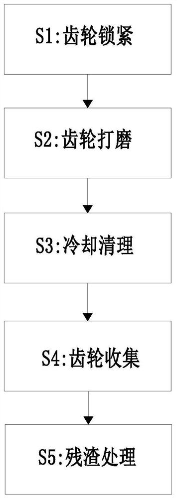
Precision gear manufacturing process
A kind of gear manufacturing and precision technology, which is applied to gear tooth manufacturing devices, manufacturing tools, belts/chains/gears, etc., and can solve problems such as gear tooth deformation, affecting gear transmission accuracy, and inability to polish.
- Summary
- Abstract
- Description
- Claims
- Application Information
AI Technical Summary
Problems solved by technology
Method used
Image

Examples
Embodiment Construction
[0029] The specific embodiment of the present invention will be described in further detail by describing the embodiments below with reference to the accompanying drawings, the purpose is to help those skilled in the art to have a more complete, accurate and in-depth understanding of the concept and technical solutions of the present invention, and To facilitate its practice, but not as a limitation of the invention.
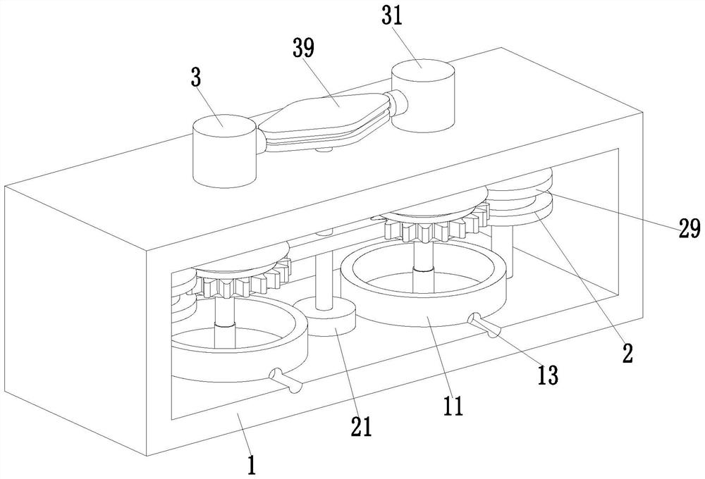
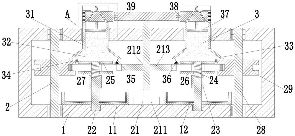
[0030] See attached Figure 1-6 As shown, a precision gear manufacturing process uses a precision gear manufacturing device. The precision gear manufacturing device includes a support frame 1, a grinding mechanism 2 and a cooling and cleaning mechanism 3. The cross section of the support frame 1 is a rectangular structure. A grinding mechanism 2 is installed in the middle part of the lower end surface of the support frame 1, and a cooling and cleaning mechanism 3 is connected to the polishing mechanism 2, and the cooling and cleaning mechanism 3 is installed on ...
PUM
 Abstract
Description
Claims
Application Information