Multiple-resonance antenna

a multi-resonance antenna and antenna technology, applied in the direction of antennas, antenna feed intermediates, basic electric elements, etc., can solve the problem that right-handed antennas cannot be used for the above-mentioned applications, and achieve the effect of easy subjecting to impedance matching

Inactive Publication Date: 2009-02-12
TOYOTA JIDOSHA KK
View PDF3 Cites 8 Cited by
  • Summary
  • Abstract
  • Description
  • Claims
  • Application Information

AI Technical Summary

Benefits of technology

[0014]The present invention provide a small multiple-resonance antenna that resonates at narrowly gapped frequencies and that may be easily subjected to impedance matching at the feed point.

Problems solved by technology

Antennas for use used in these systems are preferably small, because their installation space is occasionally limited, and can able to use both the two frequency bands, namely the 300 MHz band and the 400 MHz band, because their installation space is occasionally limited.
Since there is a wide gap between the frequencies of the first and second resonances as described above, right-handed antennas cannot be used for the applications mentioned above.

Method used


Image

  • Multiple-resonance antenna
  • Multiple-resonance antenna
  • Multiple-resonance antenna

Examples


first embodiment

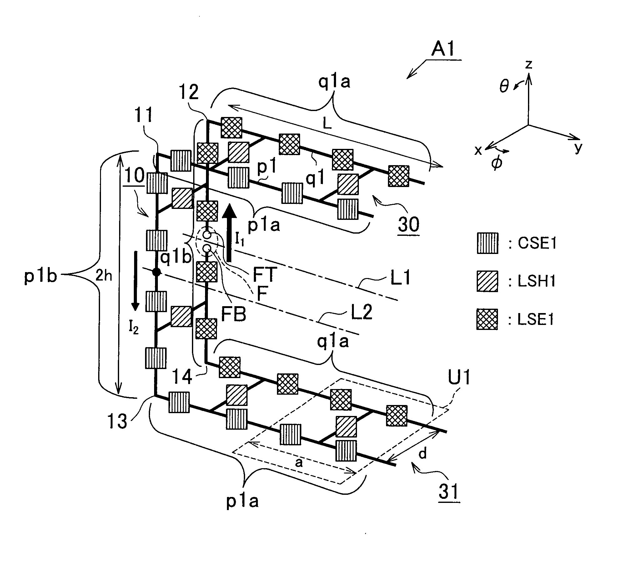
[0057]FIG. 1 is a perspective view of a dipole antenna A1 in accordance with the invention. The dipole antenna A1 is composed of two parallel metal wires p1, q1 as its basic structure, and six unit circuits U1 of length (the dimension in the direction parallel to the metal wires p1, q1) a and width (the gap between the metal wires p1, q1) d connected in the longitudinal direction of the metal wires p1, q1.

[0058]The unit circuits U1 are each composed of two capacitors CSE1, as an example of the first capacitor of the present invention, connected in series on a part of the metal wire p1, two inductors LSE1, as an example of the second inductor of the present invention, connected in series on a part of the metal wire q1, and a tie portion that ties the metal wires p1 and q1 via an inductor LSH1, as an example of the second inductor of the present invention. The inductors LSE1 are provided to adjust the two resonance frequencies and the impedance.

[0059]The dipole antenna A1 has a base p...

second embodiment

[0068]FIG. 6 is a plan view of a dipole antenna A2 in accordance with the present invention. The dipole antenna A2 has, as its basic structure, two parallel metal wires p2, q2 which are disposed in an x-y plane. The dipole antenna A2 has a base portion 20 extending in the polarization direction of radiation waves from the metal wires p2, q2 (y-axis direction), and extended portions 40, 41 provided in the plane in which the base portion 20 is disposed and formed to be bent at an angle of 90 degrees with respect to the base portion 20. A feed point F constituted of points FT, FB is provided at the middle of the base portion 2 of the metal wire q2. The metal wire q2 has the same shape as the metal wire q1. That is, the metal wire q2 has a shape with two bent portions (21, 23) at an angle of 90 degrees (squared U-shape) so as to be symmetric with respect to a symmetry axis L3 passing through the feed point F and extending perpendicularly to the y-axis. The metal wire p2 is disposed on t...

third embodiment

[0074]In the present invention, the dipole antenna A1 is formed using a multilayer printed circuit board. That is, as shown in FIG. 10, the dipole antenna A1 may be formed by forming the metal wire p1 and the capacitors CSE1 on the front surface of a substrate 10 with thickness d, the metal wire q1 and the inductors LSE1 on the back surface of the substrate 10, and the inductors LSH1 in through holes 11.


PUM


Abstract

A dipole antenna includes a plurality of parallel metal wires as its basic structure, and a plurality of identical or similar unit circuits arranged in a row in an extending direction of the plurality of metal wires and connected with each other. The unit circuits each have a tie portion that connects the metal wires with each other via at least one first inductor, and at least one first capacitor provided on at least one of the metal wires. The plurality of metal wires each have a base portion and an extended portion, and the plurality of metal wires are each bent such that the extended portion extends at an angle of 90 degrees with respect to the base portion.

Description

INCORPORATION BY REFERENCE[0001]The disclosures of Japanese Patent Application No. 2007-313967 filed on Dec. 4, 2007 and Japanese Patent Application No. 2007-203400 filed on Aug. 3, 2007 including the specifications, drawings and abstracts are incorporated herein by reference in their entirety.BACKGROUND OF THE INVENTION[0002]1. Field of the Invention[0003]The present invention relates to a small multiple-resonance antenna, more specifically a dipole antenna and an inverted-L antenna that includes a plurality of parallel metal wires as its basic structure and a plurality of identical or similar unit circuits arranged in a row in the direction of the metal wires and connected with each other.[0004]2. Description of the Related Art[0005]As stated in R. A. Shelby, D. R. Smith, and S. Schults, “Experimental verification of a negative index of refraction”, Science, vol. 292, pp. 77-79, April 2001, left-handed materials have been studied and applied to antennas vigorously since their appe...

Claims


Application Information

Patent Timeline
Patent Type & Authority Applications(United States)
IPC IPC(8): H01Q9/16
CPCH01Q1/38H01Q5/364H01Q23/00H01Q19/26
Inventor IIZUKA, HIDEOIDE, NOBUHIRO
Owner TOYOTA JIDOSHA KK
Why Eureka
Try Eureka