Antenna module whose antenna characteristics are not adversely affected by a mother board

a technology of antenna characteristics and mother boards, applied in the direction of antennas, antenna details, antenna feed intermediates, etc., can solve the problems of difficult to achieve high reliability in both manufacturability, and achieve the effect of improving space factor, avoiding the size of insulative substrates, and easy attaining of impedance matching

Inactive Publication Date: 2005-04-19
ALPS ALPINE CO LTD
View PDF7 Cites 9 Cited by
  • Summary
  • Abstract
  • Description
  • Claims
  • Application Information

AI Technical Summary

Benefits of technology

[0010]In the above-configured antenna module, since the antenna structure is not of a monopole but of a half-wave dipole in which the pair of radiation elements are fed at the center, its antenna characteristics are not adversely affected by a mother-board-side ground conductor. Since the overall length of the snaked, band-shaped conductor extending in “meander” form may be set to about ¼ of the free space wavelength λ of radio waves used, the longitudinal dimension of a patterning region of the snaked, band-shaped conductor can be much smaller than λ / 4. That is, one of the pair of radiation elements of the dipole antenna can be patterned in a relatively narrow region, whereby increase in the size of the insulative substrate can be avoided. Further, since the capacitance of the snaked, band-shaped conductor increases as its “meandering” pitch is decreased, impedance matching can be attained easily.
[0011]In the above configuration, the pair of radiation elements may be arranged so as to generally assume an L-shape in a plan view. In this case, since the radiation element scan bear ranged along two adjoining sides of the insulative substrate, the circuit unit and the connector can be arranged in the remaining region on the insulative substrate without being forced to be confined there, which means improvement in the space factor. This is favorable for miniaturization of the insulative substrate. The pair of radiation elements may be the snaked, band-shaped conductor and a chip-type antenna. In this case, the miniaturization of the insulative substrate is made easier than in the case where both of the radiation elements are a snaked, band-shaped conductor.

Problems solved by technology

However, the very reason that the above conventional antenna module is compact enough to be useful, i.e. the antenna module is of a monopole type that utilizes a mirror principle in which the presence of the ground conductor 5 allows the spiral, band-shaped conductor 2b to resonate in the same manner as in a half-wave dipole, creates a problem.
This means that it is difficult to attain high reliability in both manufacturability, in addition to operability as it is not unlikely that the relative position may vary significantly, for example due to temperature fluctuations.

Method used


Image

  • Antenna module whose antenna characteristics are not adversely affected by a mother board
  • Antenna module whose antenna characteristics are not adversely affected by a mother board

Examples


Embodiment Construction

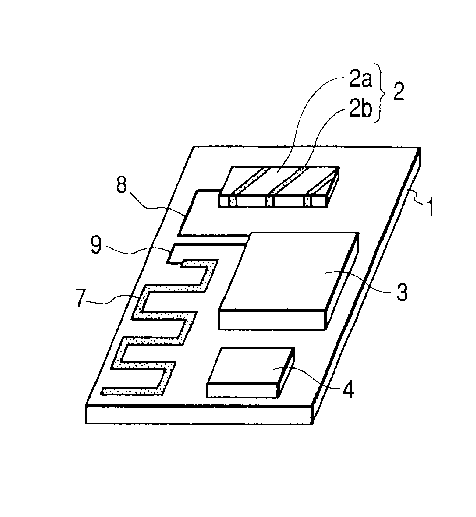
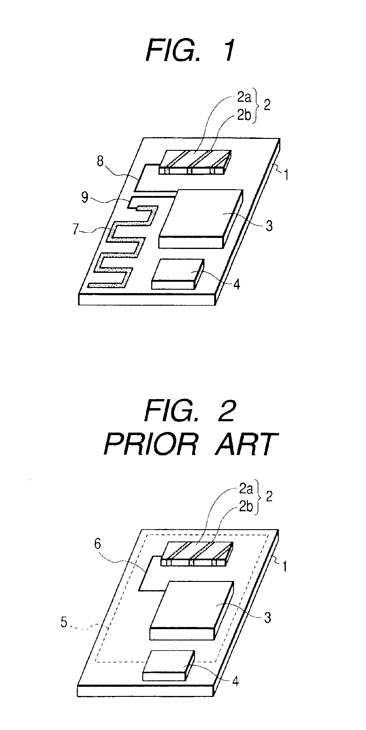
[0014]An embodiment of the present invention will be hereinafter described with reference to FIG. 1, which illustrates an antenna module according to the embodiment of the invention. Components in FIG. 1 having corresponding components in FIG. 2 are given the same reference symbols as the latter.

[0015]The antenna module shown in FIG. 1 is generally configured in such a manner that a chip-type antenna 2 and a snaked, band-shaped conductor 7 as a pair of radiation elements that are fed at the center, a circuit unit 3 in which a transmission / reception circuit connected to feeder lines 8 and 9 for the respective radiation elements 2 and 7 is covered with a shield case, and a connector 4 that connects, to a mother-board-side external circuit, lead lines leading from the transmission / reception circuit are arranged on an insulative substrate 1 that is mounted on the mother board (not shown) of a personal computer or the like.

[0016]The chip-type antenna 2 is of a known type in which a band-...


PUM


Abstract

A chip-type antenna and a snaked, band-shaped conductor as a pair of radiation elements fed at the center, a circuit unit having a transmission/reception circuit that is connected to respective feeder lines for the radiation elements, and a connector that connects, to an external circuit, lead lines leading from the circuit unit are arranged on an insulative substrate to be mounted on a mother board. The pair of radiation elements extend along two adjoining sides of the insulative substrate so as to generally assume an L-shape in a plan view.

Description

BACKGROUND OF THE INVENTION[0001]1. Field of the Invention[0002]The present invention relates to an antenna module that is mounted on the mother board of an electronic apparatus such as a personal computer. In particular, the invention relates to an antenna module that is suitable for short-distance radio data communication.[0003]2. Description of the Related Art[0004]In recent years, radio data transfer methods that enable short-distance information exchange by transmitting and receiving radio waves in a prescribed frequency band (e.g., a 2.4-GHZ band) have come to attract much attention. With the spread of such a technology, in the future, it will become more necessary to provide an antenna module for transmission and reception of communication data on the mother board of an electronic apparatus such as a personal computer.[0005]FIG. 2 illustrates a conventional antenna module of the above kind. As shown in FIG. 2, the antenna module is generally configured in such a manner that a...

Claims


Application Information

Patent Timeline
Patent Type & Authority Patents(United States)
IPC IPC(8): H01Q1/38H01Q23/00H01Q9/04H01Q9/28H01Q9/16H01Q1/24H01Q9/26
CPCH01Q1/38H01Q23/00H01Q9/285H01Q9/16
Inventor JINUSHI, SATORU
Owner ALPS ALPINE CO LTD
Why Eureka
Try Eureka