

Radial logarithmic helix waveguide slow wave line and processing method thereof
A logarithmic spiral and slow wave line technology, applied in the field of microwave vacuum electronic devices, can solve the problems of reducing current density, affecting beam-wave interaction, limiting the efficiency of beam-wave interaction, etc.
- Summary
- Abstract
- Description
- Claims
- Application Information
AI Technical Summary
Problems solved by technology
Method used
Image

Examples
example
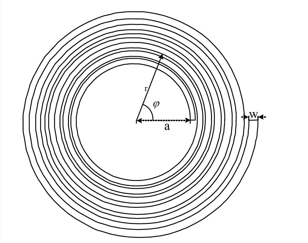
[0041] In this example, if Figure 4 As shown, in the W frequency band, the specific dimensions of the radial logarithmic helical waveguide slow wave line are as follows (unit: mm): a=16, b=0.02, h=2.65, w=1.3, w2=0.6, t=0.4 , rc=8. Its normalized phase velocity curve is shown in Figure 5 , when the center frequency is 94GHz, the operating voltage is about 102V, which is much lower than that of conventional traveling wave tubes.
[0042] In this example, the radial logarithmic helical waveguide slow wave line of the present invention uses a circular radial electron optical system to work, such as Figure 7 shown. 1 is a cylindrical cathode, which adopts thermal emission. The radial ribbon-shaped electron beam is emitted from the cylindrical side of the cathode. Since the radius of the cathode can be made very large, the current it can emit is much higher than that used by conventional traveling wave tubes. The cathode, which is also one of the advantages of the radial bea...
PUM
 Abstract
Description
Claims
Application Information