Antenna apparatus

a technology of antenna and circuit, applied in the direction of waveguide type devices, resonant antennas, radiating element structural forms, etc., can solve the problems of increasing the number of components forming matching circuits b>60/b>, and it is considered relatively difficult to manufacture this apparatus at low cos

Inactive Publication Date: 2007-03-13
PANASONIC CORP
View PDF5 Cites 7 Cited by
  • Summary
  • Abstract
  • Description
  • Claims
  • Application Information

AI Technical Summary

Benefits of technology

[0018]By virtue of the described configuration, an antenna apparatus allowing impedance matching thereof to be achieved easily and being economical can be realized and it is useful for application to such apparatuses as vehicle-mounted mobile radio apparatuses.

Problems solved by technology

Hence, there has been a problem that the number of components forming matching circuit 60 increases.
Hence, it is considered relatively difficult to manufacture this apparatus at low cost.
However, it seems to be a problem with this type that it, due to its configuration, becomes high-profiled as an antenna apparatus.

Method used


Image

  • Antenna apparatus
  • Antenna apparatus
  • Antenna apparatus

Examples


first exemplary embodiment

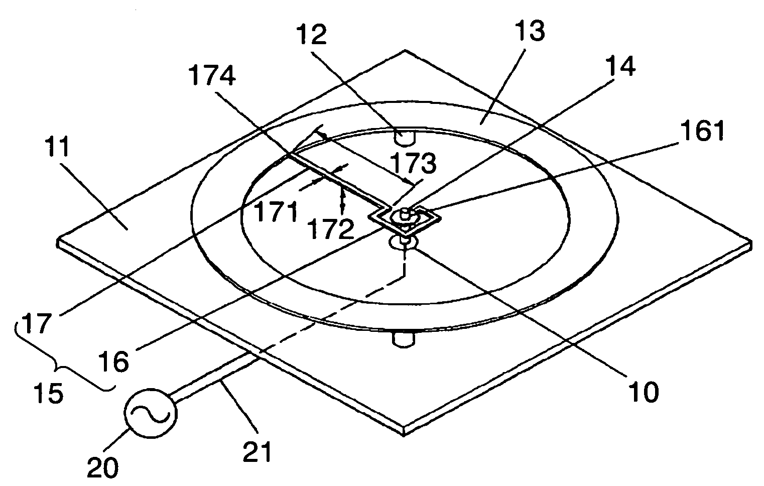
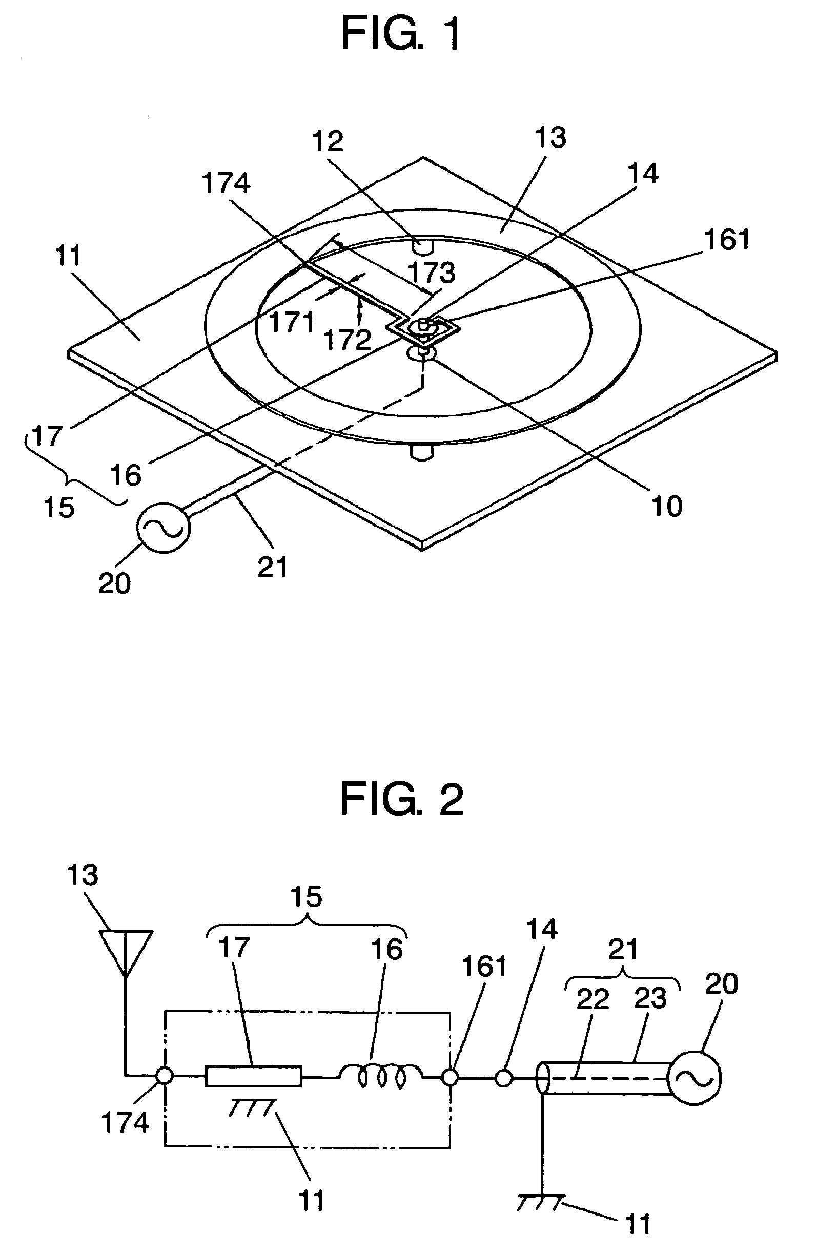
[0027]An antenna apparatus according to a first exemplary embodiment of the present invention will be described below with reference to FIG. 1 and FIG. 2. FIG. 1 is a perspective view of the antenna apparatus according to the first exemplary embodiment of the present invention and FIG. 2 is a circuit diagram of the antenna apparatus. The antenna apparatus is mainly formed of grounded electrode 11 made of a flat metal plate, ring-shaped ring electrode 13 held a predetermined distance apart from grounded electrode 11, feeding terminal 14, and connection member 15 having a function of an impedance matching circuit, and to the same are connected coaxial line 21 and signal circuit unit 20.

[0028]Ring electrode 13 is supported by a plurality of supporting members 12 made of an insulating material so as to be held at a predetermined distance from grounded electrode 11 and disposed to confront grounded electrode 11.

[0029]Ring electrode 13 is made, for example, of a copper alloy material cond...

second exemplary embodiment

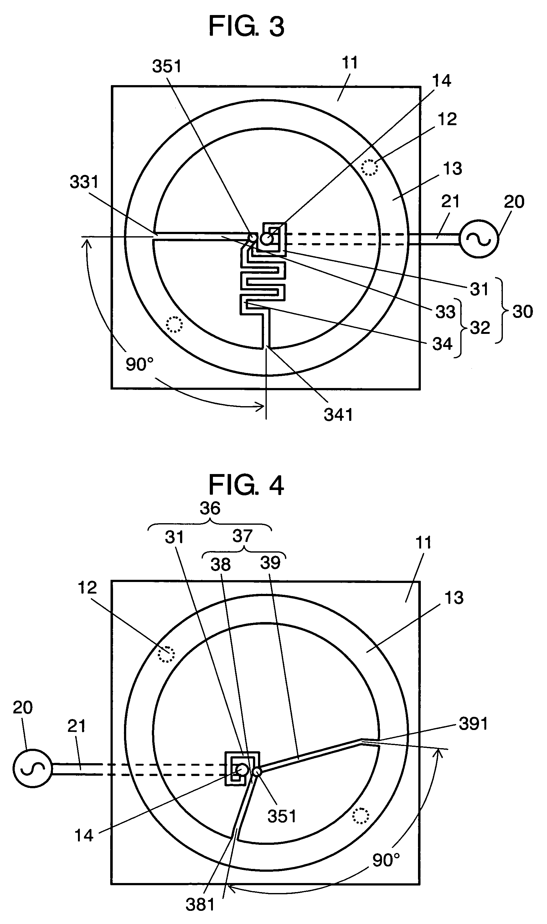
[0043]FIG. 3 is a plan view of an antenna apparatus according to a second exemplary embodiment of the present invention. The antenna apparatus of the present embodiment is characterized by that transmission line portion 32 of connection member 30 is constituted of first transmission line portion 33 and second transmission line portion 34.

[0044]Further, first transmission line portion 33 and second transmission line portion 34 each have one end thereof connected to termination point 351 of impedance converting portion 31. On the other hand, the other end 331 of first transmission line portion 33 and the other end 341 of second transmission line portion 34 are connected to ring electrode 13 such that their ends 331, 341 form an angle of substantially 90° therebetween.

[0045]Further, there is provided a difference between the electric length of first transmission line portion 33 and the electric length of second transmission line portion 34. Namely, the electric length of first transmis...


PUM


Abstract

A ring electrode is disposed in a ring shape opposite to a grounded electrode in a flat shape at a predetermined distance therefrom. A connection member is disposed which is made up of impedance converting portion and transmission line portion, connected in series with impedance converting portion, between the inner side of ring electrode and feeding terminal. Thus, an antenna apparatus easy to achieve impedance matching thereof by use of a connection member can be economically realized.

Description

FIELD OF THE INVENTION[0001]The present invention relates to an antenna apparatus for use in such apparatuses as vehicle-mounted mobile radio apparatuses.BACKGROUND OF THE INVENTION[0002]Recently, mobile radio apparatuses such as ETC (Electronic Toll Collection) systems have come into wide use. As antenna apparatus to be used in such radio apparatuses, there are proposed ring antenna apparatuses not employing an expensive dielectric substrate.[0003]FIG. 5 is a perspective view of an example of such an antenna apparatus and FIG. 6 shows a circuit diagram of the same.[0004]The conventional antenna apparatus is constructed of wiring substrate 40, ring electrode 43, and matching circuit 60, with, in addition, coaxial line 51 and signal circuit unit 50 connected to the same. Wiring substrate 40 has grounded electrode 41 made of copper foil formed on its top face and wiring pattern 45 in a predetermined shape formed on its rear side. Ring electrode 43 in a ring shape is supported by a plu...

Claims


Application Information

Patent Timeline
Patent Type & Authority Patents(United States)
IPC IPC(8): H01Q1/36H01P5/08H01Q13/08H01Q1/38H01Q9/04
CPCH01Q9/0464
Inventor MASUTANI, TAKESHI
Owner PANASONIC CORP
Why Eureka
Try Eureka