Antenna device and portable radio communication device comprising such an antenna device

a portable radio communication and antenna device technology, applied in the direction of resonant antennas, substantially flat resonant elements, antenna earthings, etc., can solve the problems of difficult to find a configuration of passive antennas that provides a wide operating band, limited number of frequency bands in passive antennas, and some constraints on the antenna configuration. to achieve the effect of easy control

Active Publication Date: 2010-10-05
SAMSUNG ELECTRONICS CO LTD
View PDF16 Cites 25 Cited by
  • Summary
  • Abstract
  • Description
  • Claims
  • Application Information

AI Technical Summary

Benefits of technology

[0013]It has been suggested that the radiating elements should be divided in two parts and connected with a switch to thereby achieve the above purpose. On such switch element may be a diode. Since, however, diodes are not ideal components it has been discovered that they may cause sharp harmonics which may not be tolerated in some standards. The present inventors have discovered that by providing the diode, or switch, on the ground plane, where the currents in the diode are much smaller compared to currents in the diode if provided on the radiating element, these harmonics are not at all as disturbing, and it is easier to design an antenna keeping within limits defined by different standards.
[0015]Thus, there is provided a multi-band antenna device having an antenna volume as small as about 2 cm3 which means that the size of the antenna is remarkably reduced compared to standard multi-band patch antennas but still with maintained or improved RF performance. Also, the bandwidths of the antenna device according to the invention can be improved compared to corresponding prior art devices but without any increase in size, which is believed to be a result of the use of the basic frequency mode of the antenna structure. As an example thereof, bandwidths of as much as 15% of the centre frequency of the higher frequency band have been obtained as compared to 9-10% in conventional prior art antenna devices.
[0019]By dividing the ground plane in two parts and connecting these two parts with a switch it is possible to control the configuration of the ground plane and thereby the resonance frequency of the antenna.
[0022]By using a PIN diode as a switch to state of the switch is easily controllable by providing a voltage input.
[0023]According to a variant of the present invention a high pass filter is connected between the first and second ground plane portions, which high pass filter allows the radio frequency signals to pass. This provides for the possibility to have a slit with a controllable length in the ground plane.
[0028]According to a variant of the present invention a filter is provided between the feeding portion for feeding a control voltage to the switch and the second ground plane means. According to a variant of the present invention the filter is a low pass filter blocking signals at frequencies equal to and higher than the lower frequency band of the at least a first and a second frequency bands. This prevents high frequency signals from reaching the control logic connected to the feeding portion.

Problems solved by technology

However, the application of internal antennas in a mobile phone puts some constraints on the configuration of the antenna, such as the dimensions of the radiating element or elements, the exact location of feeding and grounding portions etc.
These constraints may make it difficult to find a configuration of the antenna that provides a wide operating band.
The number of frequency bands in passive antennas is limited by the size of the antenna.
Although this provides for a frequency control, the antenna device still has a large size and is not well adapted for switching between two or more relatively spaced apart frequency bands, such as between the GSM and DAMSP and / or DCS and PCS bands.
A problem in prior art antenna devices is thus to provide a multi-band antenna of the PIFA type with a small size and volume and broad frequency bands which retains good performance.

Method used


Image

  • Antenna device and portable radio communication device comprising such an antenna device
  • Antenna device and portable radio communication device comprising such an antenna device
  • Antenna device and portable radio communication device comprising such an antenna device

Examples


Embodiment Construction

[0039]In the following description, for purposes of explanation and not limitation, specific details are set forth, such as particular techniques and applications in order to provide a thorough understanding of the present invention. However, it will be apparent to one skilled in the art that the present invention may be practiced in other embodiments that depart from these specific details. In other instances, detailed descriptions of well-known methods and apparatuses are omitted so as not to obscure the description of the present invention with unnecessary details.

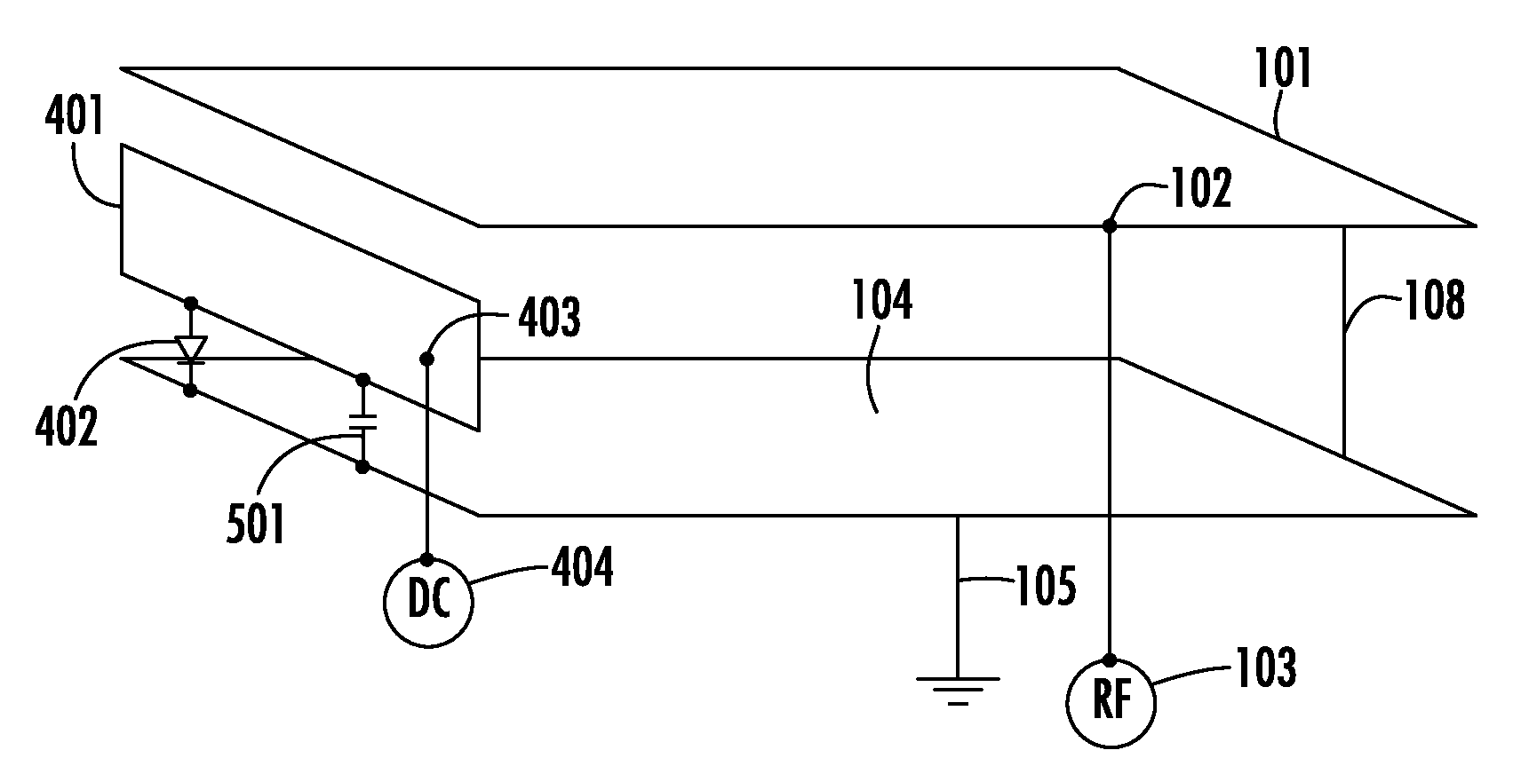
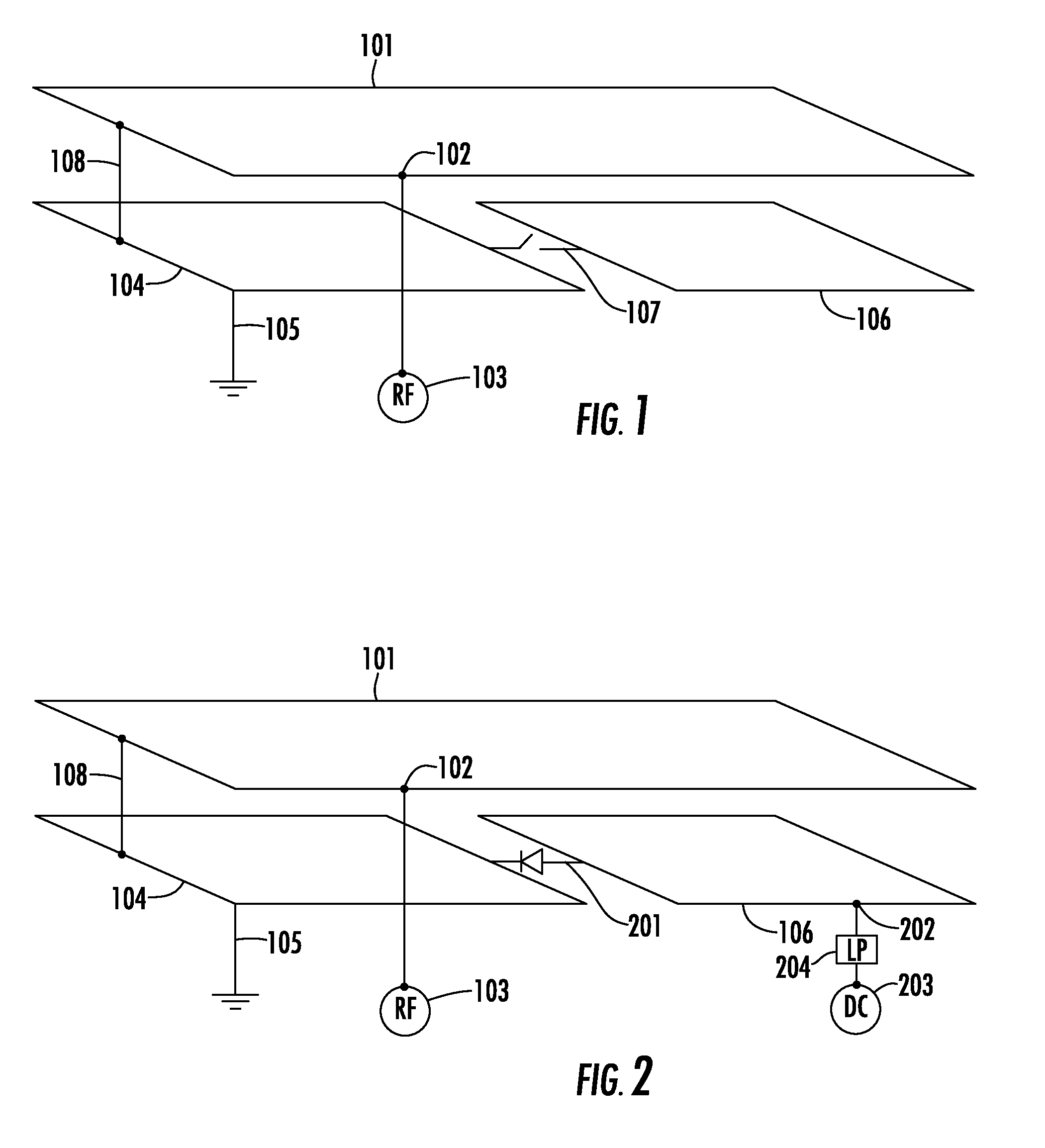
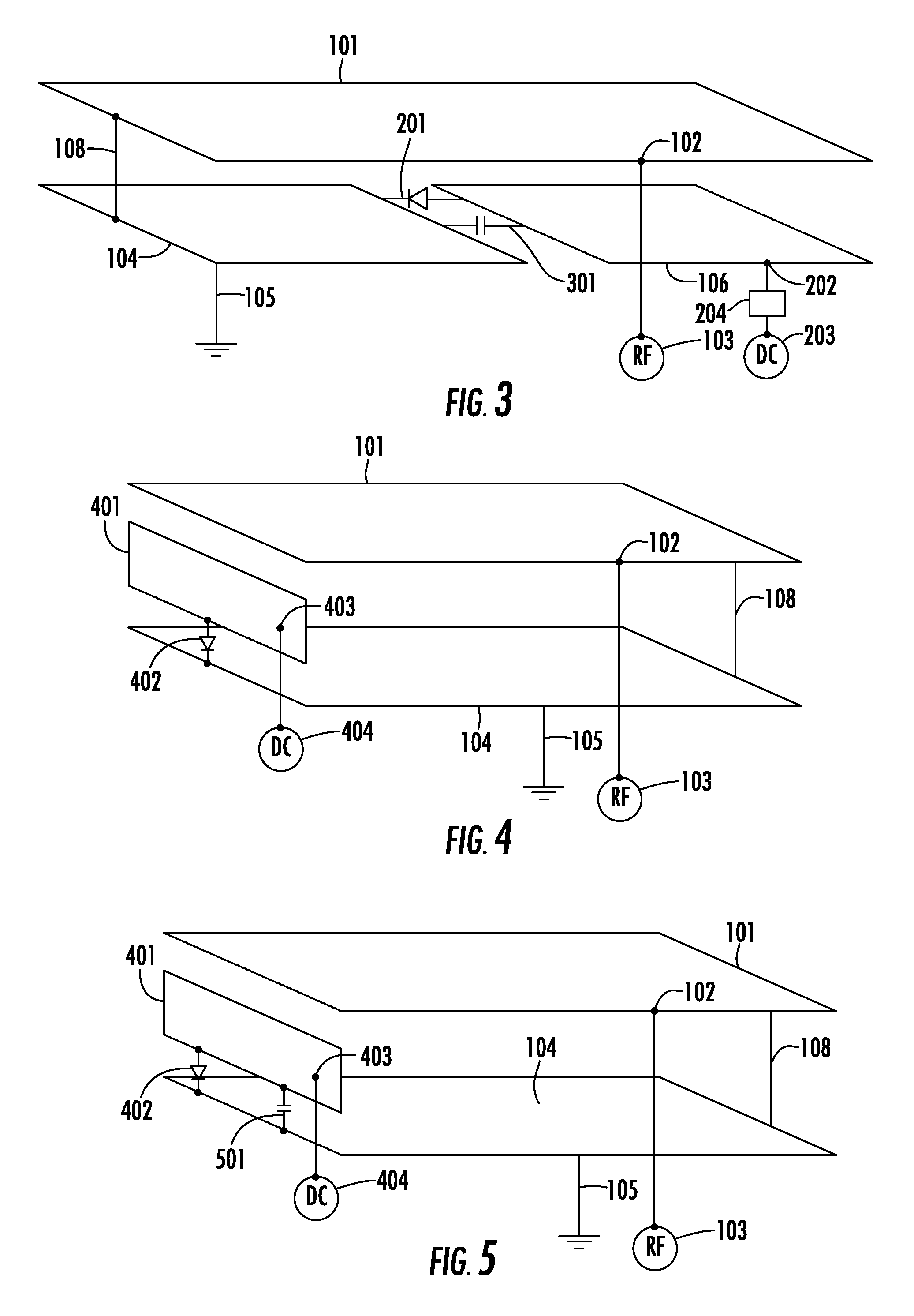
[0040]FIG. 1 is a schematic perspective view of a first variant of the invention showing a radiating element 101 having a feeding point 102 being connectable to a radio frequency signal feed 103, such as a portable radio telecommunication device (not shown). Even though the radiating element 101 is shown as a substantial rectangular sheet it may take other forms to be tuned to the desired frequency band as is much discu...


PUM


Abstract

The present invention comprises an antenna device for a portable radio communication device operable in at least a first and a second frequency band. The antenna device comprises a first electrically conductive radiating element having a feeding portion connectable to a feed device (RF) of the radio communication device for feeding and receiving radio frequency signals, a first ground plane portion arranged at a distance from the first radiating element, a second ground plane portion, and a controllable switch arranged between the first and second ground plane portion for selectively interconnecting or disconnecting the first and second ground plane portion.

Description

FIELD OF INVENTION[0001]The present invention relates generally to antenna devices and more particularly to a controllable internal multi-band antenna device for use in portable radio communication devices, such as in mobile phones. The invention also relates to a portable radio communication device comprising such an antenna device.BACKGROUND[0002]Internal antennas have been used for some time in portable radio communication devices. There are a number of advantages connected with using internal antennas, of which can be mentioned that they are small and light, making them suitable for applications wherein size and weight are of importance, such as in mobile phones. A type of internal antenna that is often used in portable radio communication devices is the so-called Planar Inverted F Antenna (PIFA).[0003]However, the application of internal antennas in a mobile phone puts some constraints on the configuration of the antenna, such as the dimensions of the radiating element or eleme...

Claims


Application Information

Patent Timeline
Patent Type & Authority Patents(United States)
IPC IPC(8): H01Q1/38H01QH01Q1/24H01Q5/10H01Q9/04
CPCH01Q1/243H01Q1/48H01Q9/0407H01Q9/0421H01Q9/0442H01Q9/145H01Q1/24H01Q9/04H01Q9/14H01Q5/20
Inventor RUTFORS, TOMASVON ARBIN, AXEL
Owner SAMSUNG ELECTRONICS CO LTD
Why Eureka
Try Eureka