Soil two-dimensional fracture test method and test device
A fracture test and soil technology, applied in the direction of testing material strength by applying stable shear force, testing material strength by applying stable tension/pressure, etc., can solve the problem of inconvenient fracture comparison research, and it is difficult to obtain continuous distribution characteristic pressure The relationship between shear force, soil sample strain and critical stress, etc.
- Summary
- Abstract
- Description
- Claims
- Application Information
AI Technical Summary
Problems solved by technology
Method used
Image
Examples
Embodiment 1
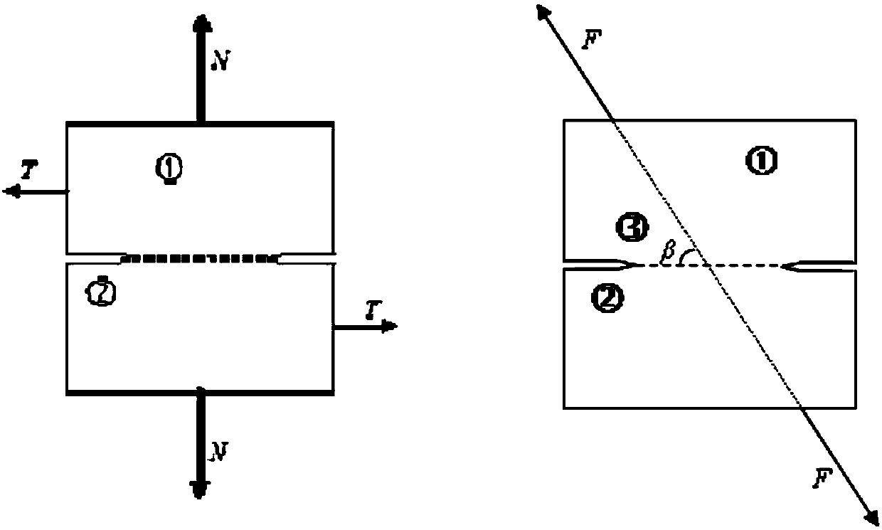
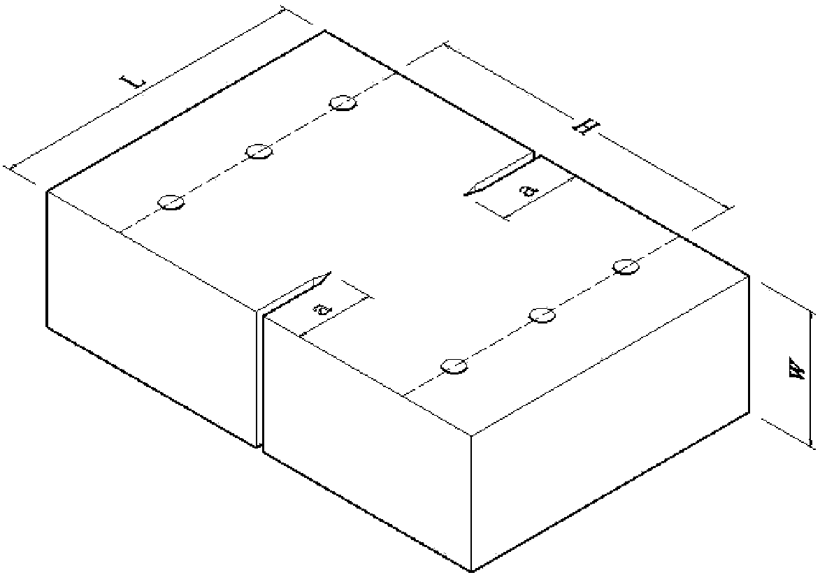
[0051] The test device includes a sample, loading plate I1 and loading plate II2. The loading plate I1 and the loading plate II 2 are identical loading plates, and together constitute a loading fixture. The installation of the test device, the test consists of pins passing through the sample fixing holes I 1-4 and the sample fixing holes II 2-4 respectively with the sample holding plate I 1-5 and the sample holding plate II 2-5 is fixed on the loading plate, and the loading rod I 1-7 and the loading rod II 2-7 are respectively fixed on the loading rod installation hole I 1-2 and the loading rod installation hole II2-2. The other ends of the loading rod I 1-7 and the loading rod II 2-7 are respectively connected to the external loading power device, and the loading rod I 1-7 and the loading rod II 2-7 are always kept on the same straight line. The start-up, loading mode, loading rate and termination operations of loading rod I 1-7 and loading rod II 2-7 are all controlled by c...
Embodiment 2
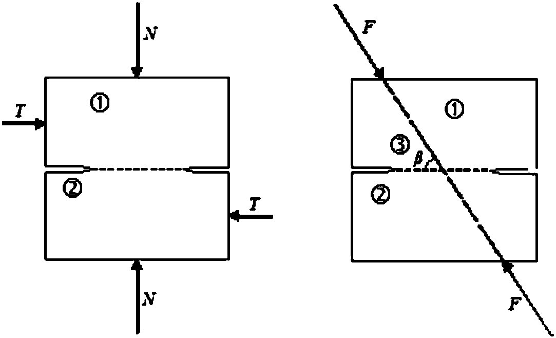
[0063] The test device includes a sample, loading plate I1 and loading plate II2. The loading plate I 1 and the loading plate II 2 are identical loading plates, and together constitute a loading fixture. The installation of the test device, the test consists of pins passing through the sample fixing holes I 1-4 and the sample fixing holes II 2-4 respectively with the sample holding plate I 1-5 and the sample holding plate II 2-5 is fixed on the loading plate, and the loading rod I 1-7 and the loading rod II 2-7 are respectively fixed on the loading rod installation hole I 1-2 and the loading rod installation hole II2-2. The other ends of the loading rod I 1-7 and the loading rod II 2-7 are respectively connected to an external loading power device, and the loading rod I1-7 and the loading rod II 2-7 are always kept on the same straight line. The start-up, loading mode, loading rate and termination operations of loading rod I 1-7 and loading rod II 2-7 are all controlled by co...
Embodiment 3
[0075] The test device includes a sample, loading plate I1 and loading plate II2. The loading plate I1 and the loading plate II 2 are identical loading plates, and together constitute a loading fixture. The installation of the test device, the test consists of pins passing through the sample fixing holes I 1-4 and the sample fixing holes II 2-4 respectively with the sample holding plate I 1-5 and the sample holding plate II 2-5 is fixed on the loading plate, and the loading rod I 1-7 and the loading rod II 2-7 are respectively fixed on the loading rod installation hole I 1-2 and the loading rod installation hole II2-2. The other ends of the loading rod I 1-7 and the loading rod II 2-7 are respectively connected to an external loading power device, and the loading rod I 1-7 and the loading rod II 2-7 are always kept on the same straight line. The start-up, loading mode, loading rate and termination operations of loading rod I 1-7 and loading rod II 2-7 are all controlled by co...
PUM
 Abstract
Description
Claims
Application Information
 - R&D
- Intellectual Property
- Life Sciences
- Materials
- Tech Scout
- Unparalleled Data Quality
- Higher Quality Content
- 60% Fewer Hallucinations
Browse by: Latest US Patents, China's latest patents, Technical Efficacy Thesaurus, Application Domain, Technology Topic, Popular Technical Reports.
© 2025 PatSnap. All rights reserved.Legal|Privacy policy|Modern Slavery Act Transparency Statement|Sitemap|About US| Contact US: help@patsnap.com


